
01 / 10 · Stainless mounting components
Investment Casting Gate Removal for Stainless Brackets
Agree gate-contact and cleanup zones before tooling so attachment removal protects the faces and clearances your bracket needs.
We review your drawing, proposed casting route and surfaces that will be machined. Mark locating faces, restricted assembly spaces and visible areas, then define the sample evidence needed for approval. The result is a clear surface agreement for a stainless investment-cast bracket, rather than an undefined request for a smooth finish.
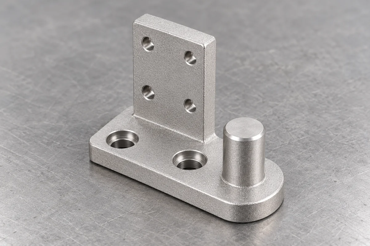
02 / 10 · Drawing review
A Cleanup Plan Before Tooling Release
Relia connects the mounting-component drawing to the proposed investment casting and secondary machining scope. For this enquiry, the important output is a marked surface plan: where an attachment may be removed, where material must remain and which faces receive a separate finishing operation.
- INPUTYour assembly referencesDrawing revision, stainless grade, quantities and the surfaces that govern fit or appearance.
- REVIEWThe proposed casting routeGate-contact locations and accessible removal areas, considered with the part geometry.
- AGREEMENTThe acceptance boundaryCleanup condition, protected features and the sample evidence needed before batch approval.
03 / 10 · Surface responsibilities
Functional Surfaces and Permitted Gate Contacts
Start with the assembly. A mounting face may need machining stock; an eye or slot may need a clear working envelope; an exposed edge may need a visual reference. These areas should not share one undefined cleanup requirement.
Locating faces, hole entrances, thin edges and mating clearances identified on your drawing.
Proposed attachment areas with access for cutting and blending, and an agreed final surface condition.
The drawing determines the actual zones. The illustrations do not identify an approved gate location for a production part.
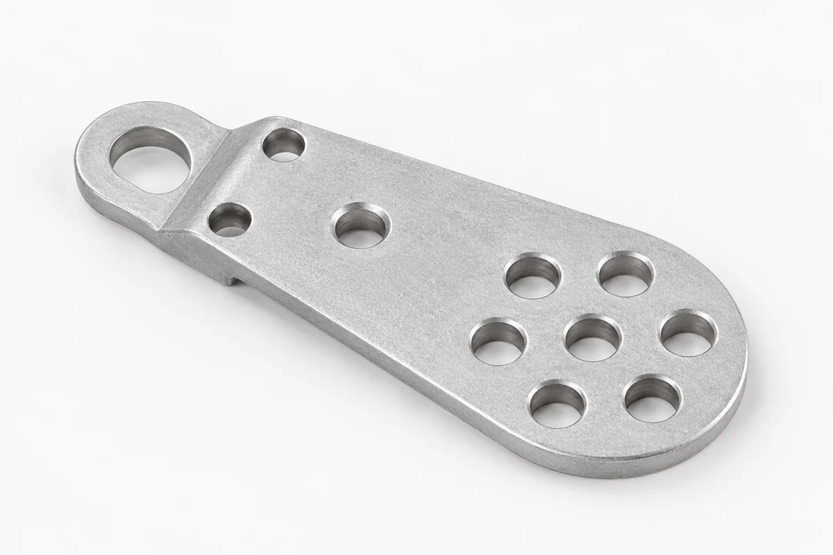
04 / 10 · Production route
Attachment Removal and Local Finishing
In investment casting, the feed attachment is removed after the metal component is separated from its mold. Cutting and local grinding may be part of that removal plan. The appropriate method and the amount of subsequent finishing depend on the alloy, access and final drawing requirements.
- SEPARATERemove the attachmentDefine the cut region without assuming it is already a finished contact surface.
- FINISHControl the local profileAgree the permitted remnant, blend or further machining. Avoid removing material beyond the approved boundary.
- CHECKInspect the resulting areaAssess the actual cleaned surface and any nearby feature affected by the operation.
Keep removal method and acceptance separate
Specifying a grinding operation alone does not define an acceptable result. Mark the required final condition, the protected neighboring surfaces and how the sample will be checked. Extra polishing is a separate request when the component needs it.
05 / 10 · Finished condition
Cast Texture and Machined Surface Boundaries
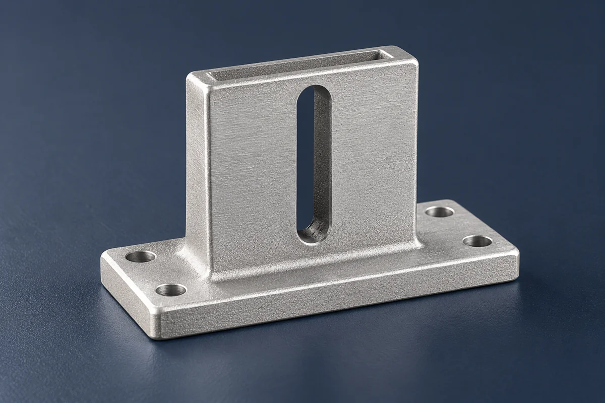
Keep an as-cast region distinct from a machined face. A locally blended attachment area may look different from the surrounding cast texture without having the same dimensional role as a finished seating face.
Where the bracket needs CNC finishing, identify the stock to retain and the datum used for the finished measurement. Where appearance matters, agree a reference and viewing conditions. A visual instruction should not silently become a roughness specification or a requirement to polish the entire component.
06 / 10 · Sample acceptance
Sample Evidence at the Cleanup Zones
Approve the sample against the marked drawing. Relia can provide agreed key dimensional inspection records with an order; the measured features and sampling frequency are defined for that order. For cleanup, also agree the photographs or visual references needed to show the local result.
| Surface responsibility | Evidence to agree | Decision before release |
|---|---|---|
| Fit or clearance near the gate | Relevant feature measurement or agreed clearance check | The cleanup has not crossed the functional limit |
| Visible cleaned area | Sample photographs or an approved surface reference | The local appearance is acceptable for the application |
| Face requiring machining | Stock and final dimensional requirements | The finished interface is accepted in its supplied condition |
Sample approval follows agreement of the drawing and acceptance requirements. Batch production is arranged after the customer approves the sample.
07 / 10 · Risk control
Defects and Cleanup Have Different Acceptance Rules
Gate-removal marks, a casting discontinuity and a dimension outside its limit are different observations. Keep their acceptance rules explicit so additional grinding is not used to hide a problem or damage a good functional feature.
Excess remaining material
Check the specified local profile and nearby assembly space. Define the required removal before accepting the sample.
Material removed too deeply
Check the actual surface against its dimensional boundary. A polished depression is not a substitute for retained wall or contact geometry.
A suspected discontinuity
Apply the agreed defect and inspection requirements. Any additional test needs defined coverage and acceptance criteria.
08 / 10 · Component references
Bracket Geometry References for Your Review
Relia's catalogue includes angle brackets, eye-ended plates, levers, slotted mounting parts and flanged cylindrical forms. Choose the component that matches your enquiry, then provide its own material and surface requirements.
The catalogue photographs are geometry references. The appearance of a component does not establish a gate location, the chemistry of a sample or an approved load rating. Your controlled drawing remains the basis for the quotation and sample review.
View investment-cast brackets, levers and mounting componentsView slotted brackets, fork ends and bored profilesPlan separate appearance acceptance for polished hardware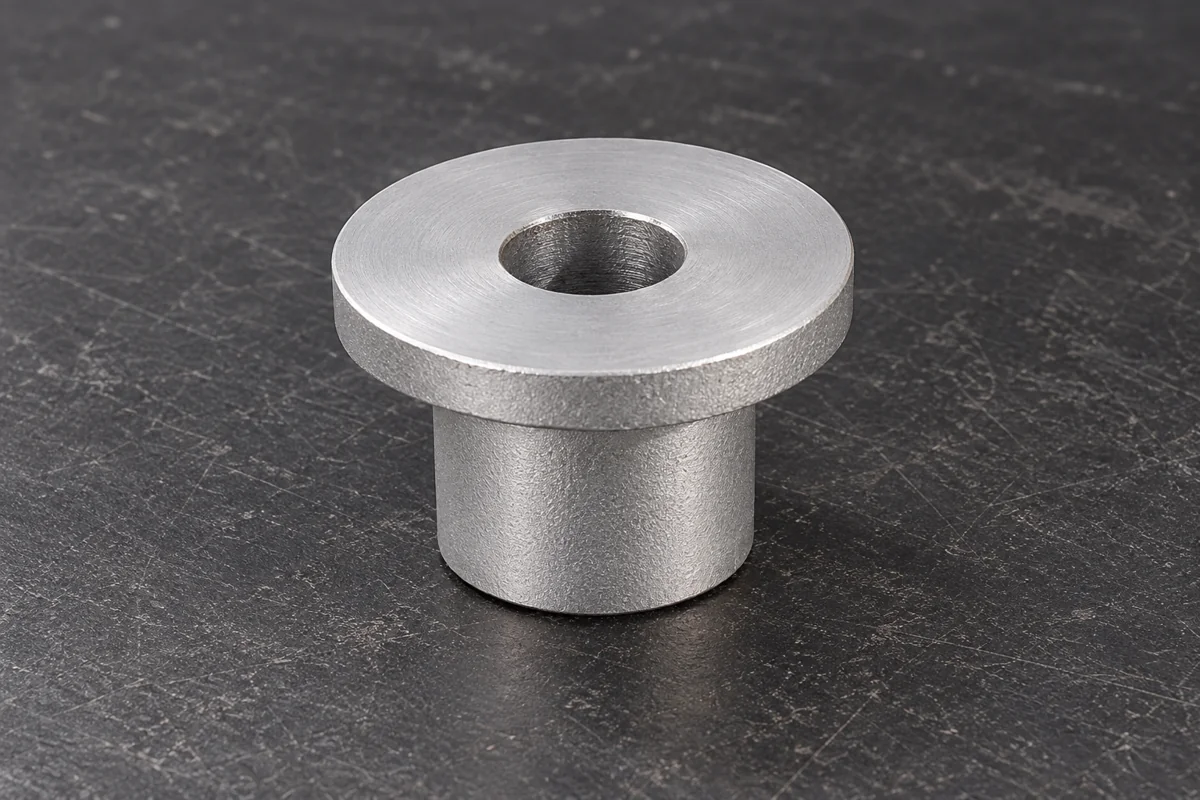
09 / 10 · Order control
Drawing Approval and Revision Control
Keep the gate-contact plan attached to the same drawing revision used for the quotation, tooling and sample approval. A later change to a hole, slot, visible face or wall may also change where removal is acceptable.
- BEFORE TOOLINGAgree the surface planRecord protected zones, proposed attachments and local finishing boundaries.
- BEFORE BATCH PRODUCTIONApprove the sampleCompare the cleaned component with the agreed drawing and evidence requirements.
- AFTER A DESIGN CHANGEReview the affected areasDecide whether tooling work, revised finishing or another sample is needed.
Include these items in the enquiry
Send the drawing revision, 3D model where available, stainless casting-grade requirement, order quantity, mating references and marked surface zones. State whether you need a casting blank or a machined component. Tooling charges, sample milestones and delivery are agreed for the actual project.
10 / 10 · Talk to the factory
Send Your Bracket Drawing and Cleanup Requirements
Send Relia the part drawing and identify the surfaces you need to protect. We can review the requested casting, cleanup and machining scope together, then agree the information needed for a useful quotation.
Relia Casting · Custom metal casting and CNC component enquiries · Qingdao, Shandong, China.
Email your drawing for reviewReview our manufacturing scope · Explore the casting factory website
- [email protected]
- Phone
- +86 185 6176 2631
- +1 404 203 0971
- Company and address
- Relia Casting
No. 96 Shuyuan Road
Qingdao, Shandong, China