
Custom Aluminium Die-Cast Housings and Motor-Base Components
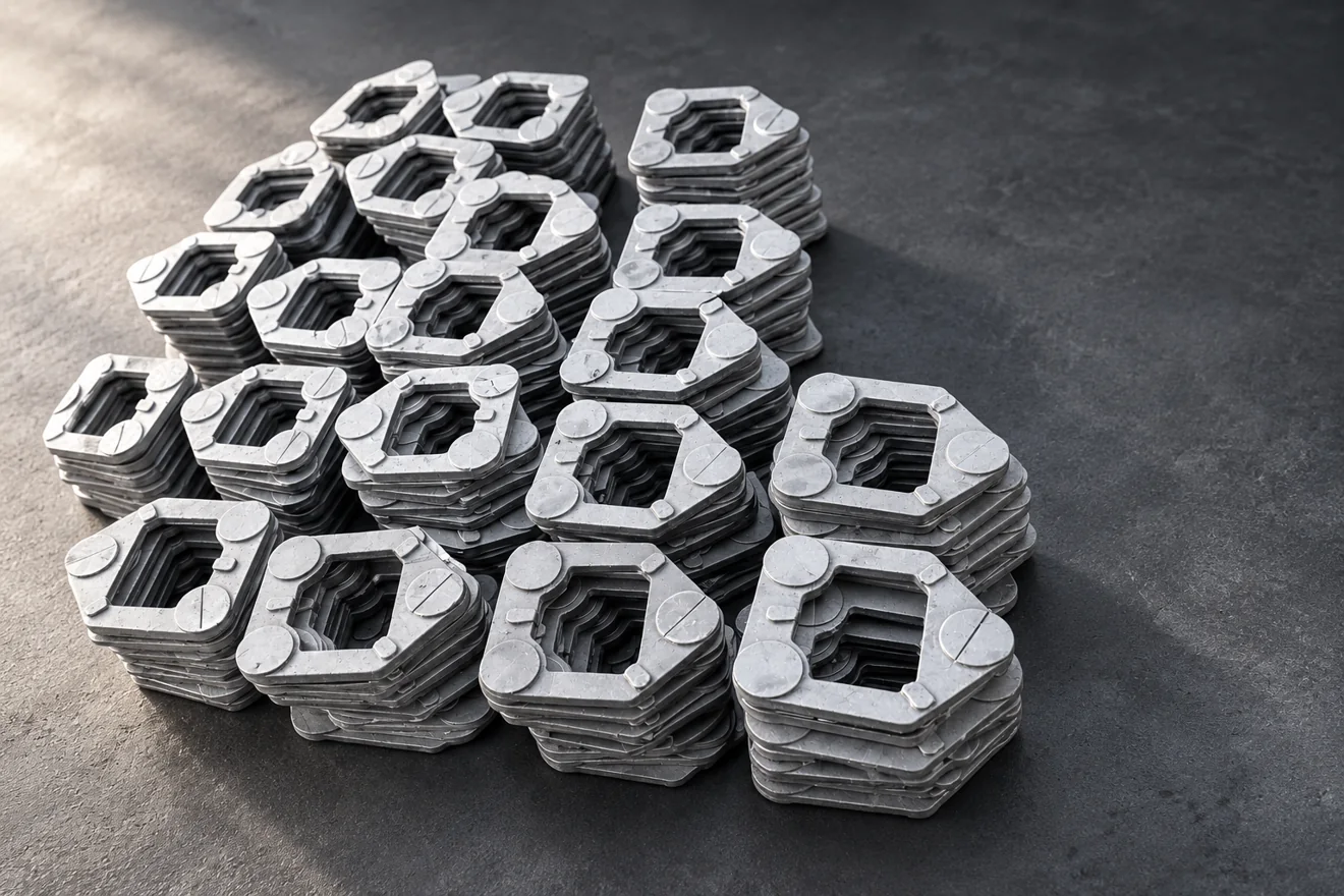
Relia reviews custom aluminium die-cast housings and motor bases around the motor location, mounting face and fixing pattern. We define the cast form, local stock and CNC contacts against your drawing, with actual alloy and delivered finish agreed before the tooling and sample scope is released.
Read the overview and page sections
We start with the motor location, fixing pattern and mating faces, then discuss the die-cast form, machining stock and final finish. This gives your equipment team a defined mounting component rather than an outside shape with an unspecified fit.
The Motor Interface Connects Tooling and Final Machining
Relia reviews the housing or motor base around the contacts used by your assembly. A central opening, raised boss and corner fixing feature have different forming and finishing needs. Relia's proposal separates cast clearances from machined locating surfaces, helping you specify the finished relationship without applying a machining tolerance to every die-cast wall.
Tooling Follows a Reviewed Component Design
Review parting direction, tool access, wall transitions and features that may need additional forming or machining. Proposed design changes are marked for your approval. Tool ownership terms, trial work and later modifications are agreed separately, so a tooling quotation explains both the initial work and the component revision it supports.
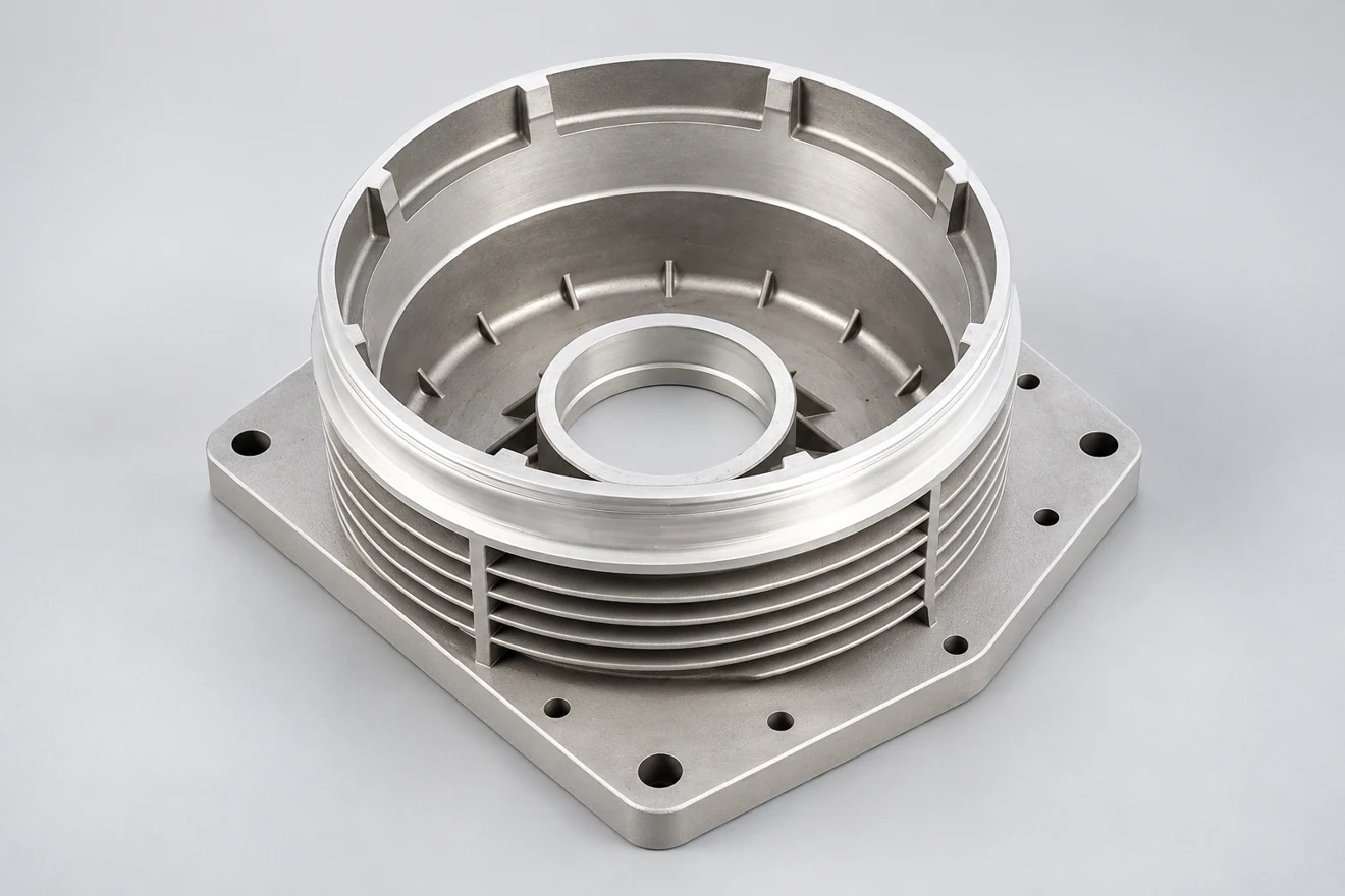
04 / 10Component decisions
Separate Die-Cast Form from Motor-Locating Features
Specify which surfaces carry the motor reference and which only provide clearance or enclosure. This keeps expensive finishing focused on useful contacts.
| Feature group | Casting review | Finished requirement |
|---|---|---|
| Walls and ribs | Fill path, section transitions and draft | Required envelope and clearance |
| Motor locating region | Stock and access at bosses or seats | Diameter, position and mating reference |
| Mounting feet or face | Support during ejection and clamping | Flatness and relation to locating features |
| Visible exterior | Parting line, gate and ejector locations | Cosmetic zones and final coating boundary |
Machine the Locating Features from a Supported Blank
Die-casting review considers parting direction, ejection and local wall changes before the tool is committed.
- Die-cast form
- Supported location
- Related contacts
- Delivered state
- Support the trimmed blank for CNC work
- Relate cut depth and integrity to the motor interface
Open the manufacturing route and detailed review
Support the trimmed blank for CNC work
Flash removal and trimming leave the blank ready for machining. The fixture should support the base without forcing a thin region into a false shape while the locating bore or mounting face is cut.
Relate cut depth and integrity to the motor interface
Relia can relate the CNC sequence to the actual motor connection and inspection datums. A finish cut may expose internal porosity, so any relevant integrity requirement belongs beside the machining depth and acceptance scope. Surface treatment is then specified with masking or allowance where it could affect the final mounting fit.
Surface Requirements Need Defined Zones
Separate visible surfaces from sealing, electrical contact or locating regions. State coating, masking and appearance requirements where applicable, including the reference or acceptance method used. A coating colour or polished rendering does not establish corrosion resistance, electrical behaviour or an ingress protection class.
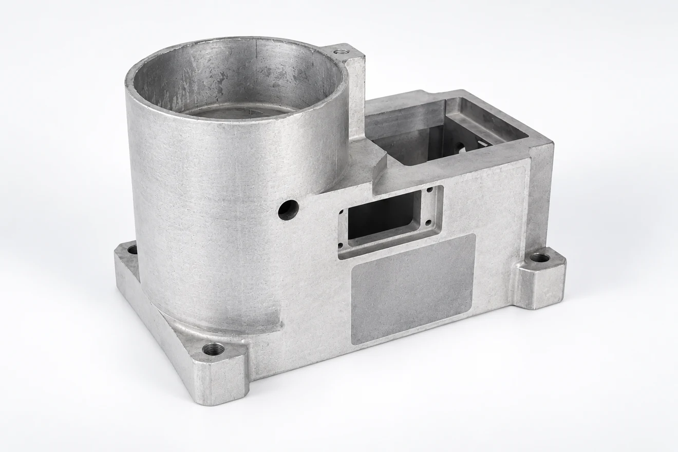
07 / 10Component decisions
Check the Part After the Operations That Affect Fit
Machining and coating can change the condition of a die-cast housing. The accepted state should match the part your assembly team receives.
| Stage | Focus | Acceptance reference |
|---|---|---|
| Die review | Wall transitions and gate or ejector positions | Allowed witness marks and machining stock |
| Trim and clean | Remove runners and unwanted sharp edges | Defined edge and visual condition |
| Machine contacts | Relate opening, bosses and fixing holes | Finished drawing and chosen datums |
| Finish and release | Protect or mask fitted surfaces as specified | Final fit and coating acceptance |
Trials Link Tooling to the Production Definition
Sample review should include the specified geometry, supplied condition and any application checks required. Record tool or drawing changes before pilot production. The recurring quotation then uses the accepted route and part definition, with quantity and delivery terms reviewed for the actual order.
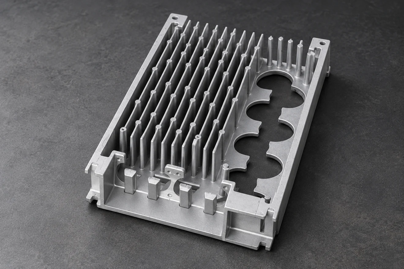
Send the Details for Your Component Review
Tell us what you need to buy and the condition you need to receive. Relia Casting will review the component, manufacturing scope and requested evidence with you before an order is agreed.
- Housing drawing and mating envelope
- Specified aluminium alloy
- Tooling and sample approval scope
- Machined interfaces and surface zones
- Quantity and applicable test requirements
No. 96 Shuyuan Road, Qingdao, Shandong, China
About our component supply · Contact details and project enquiry