
01 / 10 · Pattern assembly before tooling
Foam Pattern Joints for Ribbed Lost-Foam Housings
A complex housing may need a foam pattern assembled from several sections. Define those sections and their joints before the tooling proposal is approved.
Relia reviews the actual component, material and requested lost-foam route with your drawing. The important agreement connects the proposed pattern joints to the cast surfaces, machining stock and sample evidence your housing needs.
Review your housing pattern enquiry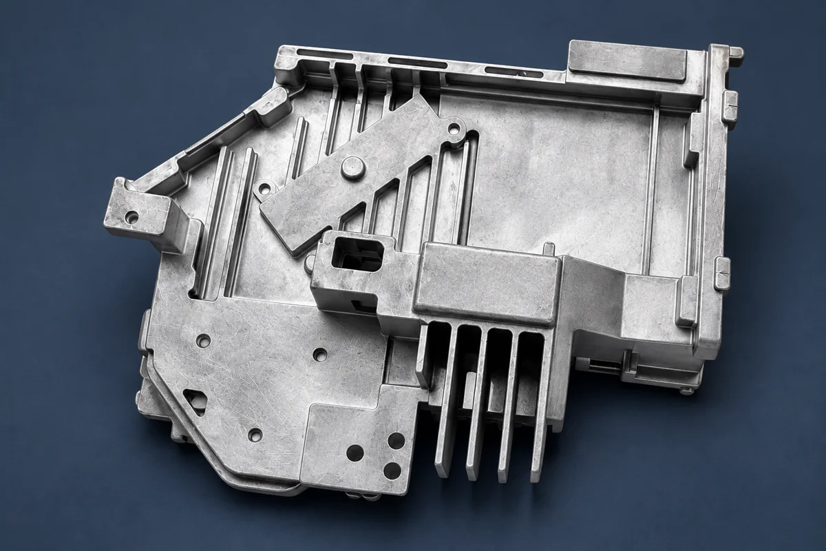
02 / 10 · Factory review
Pattern Assembly Planned Around the Cast Component
Relia starts with the selected housing and its final interfaces. A proposed pattern split should be reviewed with the component owner, especially where a joint approaches a visible region, a thin feature or an area reserved for machining.
Actual dimensions, grade, wall sections and supplied condition.
Sections, joints, support and the intended molding route.
Features, surface zones and evidence needed before batch release.
03 / 10 · The casting drawing
The Housing Sections and Assembly Boundaries
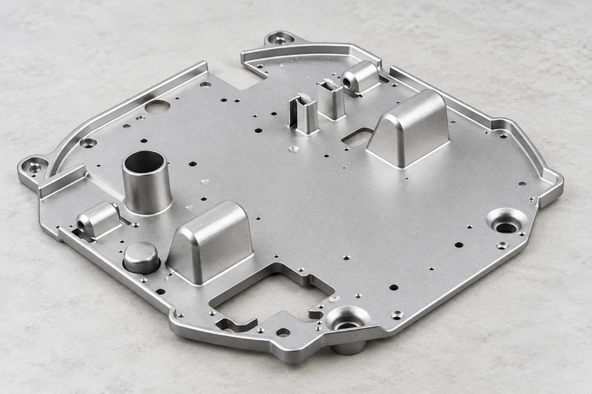
Show ribs, bosses, windows and the relationship between the housing and its mating component. Identify surfaces that must remain cast and contacts requiring secondary machining.
A 3D model helps describe the shape, while sectioned and dimensioned drawings define the acceptance requirements. Include actual overall dimensions rather than infer size or production capacity from the product image.
Review lost-foam casting component enquiries04 / 10 · Pattern-making proposal
Foam Pattern Segmentation Options
In a lost-foam route, a coated expendable foam pattern is surrounded by molding sand and replaced by metal during pouring. Where that pattern is assembled, identify the separate sections and how they relate to the final shape. The route should account for making, joining and handling the pattern before molding.
Choose a practical split
Review access around recesses, projecting ribs and enclosed or restricted features.
Define the joining responsibility
Show the intended joint locations and the surfaces or features they approach.
Lost-foam pattern design, coating and glue considerations belong in the process proposal. Their actual materials and operating parameters are agreed for the selected component.
05 / 10 · Surface planning
Joint Locations and Surface Responsibilities
Mark joint locations against the finished drawing. A joint near a window edge, mounting face or visible panel may need a different acceptance discussion from one in an accessible non-contact region.
06 / 10 · Before molding
Ribs, Bosses and Local Pattern Support
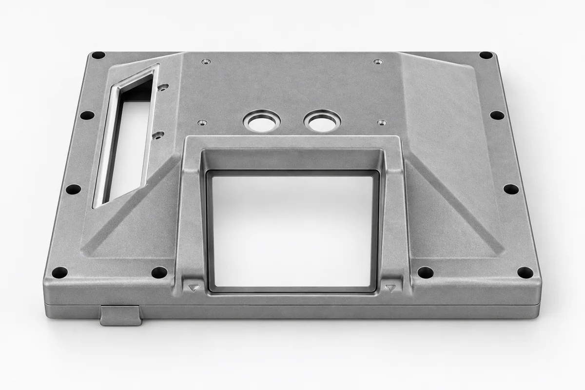
The pattern proposal should explain how its assembled shape is supported and handled. Slender ribs, projecting bosses and broad panels can create different practical handling requirements.
Check local alignment and excess near ribs, bosses, window edges and reserved machining stock.
For a lost-foam route, the expendable pattern defines the proposed casting shape. Pattern assembly, coating and molding should be considered together, rather than treated as unrelated purchasing items.
Record the handling and joining proposal
Identify the pattern sections, joint regions and handling requirements that affect the agreed geometry. Link changes to the controlled component revision and sample scope.
07 / 10 · Validation
Trial Observations and Sample Acceptance
Identify the observations needed from the trial and the final sample. A useful review records which joint regions and nearby features were evaluated, against which drawing revision.
- GEOMETRYCheck the selected featuresRelate pattern and casting observations to final mounting and section requirements.
- SURFACEReview the joint regionsUse agreed sample photographs or surface references for the actual acceptance zones.
- RELEASEApprove the defined componentObtain customer sample approval before arranging batch production.
Relia can provide agreed key dimensional records; measured characteristics and sampling frequency are specified per order.
08 / 10 · Geometry references
Housing and Plate Geometry References
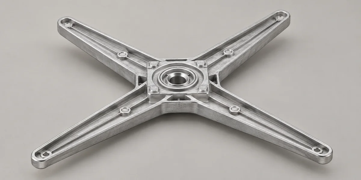
Relia lists ribbed housings, bossed plates, panels and hub-support forms for custom casting enquiries. Select the actual drawing and material before evaluating lost foam or an alternative route.
These illustrations communicate geometry. They do not establish the manufacturing history, tested performance or verified alloy of every pictured example.
View ribbed housing casting and CNC enquiriesView bossed plate casting enquiriesView the windowed equipment panel enquiryReview conversion of assemblies into integrated cast components09 / 10 · Production approval
Approve Pattern Joints Before Recurring Production
Keep the pattern-assembly proposal attached to the component revision and sample approval. A change to a rib, opening, boss or visible surface may affect the agreed joint plan.
At initial approval
Record the drawing, proposed pattern sections, surface zones and required sample evidence.
After a component change
Review affected pattern features and agree whether another trial or sample is needed.
Tooling, development charges and recurring production milestones are quoted for that explicit scope.
10 / 10 · Start a pattern review
Send Housing Sections and Protected Surface Zones
Send Relia the controlled housing drawing, section views, material requirement and quantities. Mark the functional and visible regions that should guide the pattern-joint discussion.
Email your housing enquiry- [email protected]
- Phone
- +86 185 6176 2631
- +1 404 203 0971
- Company and address
- Relia Casting
No. 96 Shuyuan Road
Qingdao, Shandong, China