
Custom Planet Pinion Carriers with Defined Bore and Post Geometry
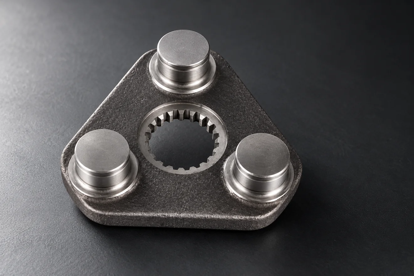
Order a custom planet pinion carrier with the centre profile, pin locations and seating plane specified as related features. Relia reviews the carrier drawing and mating requirements to define the blank, CNC work and dimensional checks. Identify separately supplied pins or gears and any assembly test; a carrier quotation covers only the components and evidence agreed for your order.
Read the overview and page sections
We use the carrier and mating-gear drawings to discuss the blank and CNC operations, including the checks needed for those relationships. The quoted scope identifies the carrier and any separately specified hardware, so a component order does not imply a complete gearbox.
Gear Location Depends on Related Manufacturing References
Relia's carrier review concentrates on the relationship between the centre profile, pin locations and seating plane. Relia connects the proposed blank with the machining needed to establish those features. This helps your engineering and purchasing teams state what must be controlled on the carrier, while keeping separate gear, pin or assembly requirements visible.
Schematic only. The released drawing defines the actual pin count, locations, profile and geometric limits.
03 / 10Component decisions
Define the Carrier Through Its Related Interfaces
Three individually correct post diameters do not establish correct gear positioning. The important dimensions describe their relationship to each other and the central axis.
| Interface | Drawing requirement | Inspection focus |
|---|---|---|
| Central profile | Spline or bore definition and engagement length | Profile or fit from the selected reference |
| Pin positions | Centre locations and required orientation | Position relative to the carrier axis |
| Seating planes | Axial support and adjoining surfaces | Face relation and assembled clearance |
| Included hardware | Separate pins, gears or fixings if ordered | Contents list and component identity |
Profiles and Fits Need Complete Specifications
Where a spline, tooth form or fitted pin feature is required, include the applicable geometry and acceptance information. Identify the mating component or gauge requirement where appropriate. A photograph of a toothed opening cannot establish compatibility, and a familiar part name is not a substitute for the profile definition.
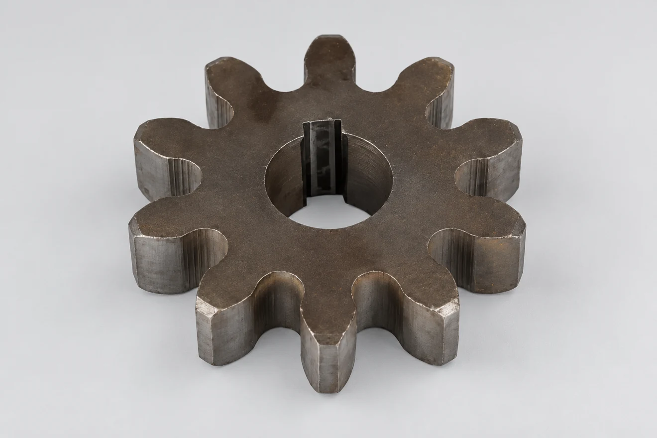
Reserve the Features Needed for the Gear-Location Cuts
The blank defines the carrier's main envelope and leaves stock at the centre, pin positions and relevant seating contacts.
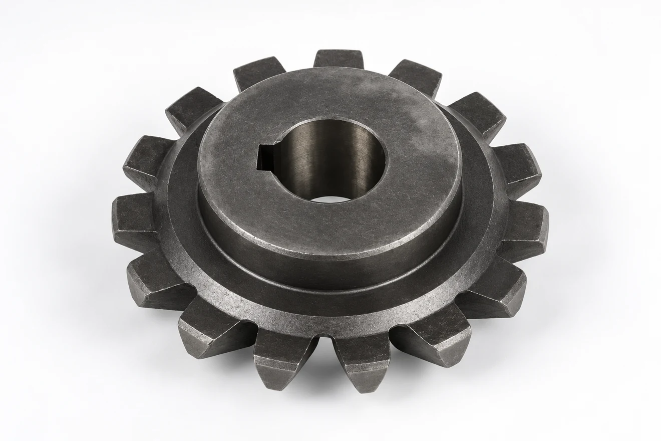
- Reserve features for gear-location cuts
- Check positional relationships beyond pin diameter
Open the manufacturing route and detailed review
Reserve features for gear-location cuts
The machining plan then establishes references that relate those features to one another. A correct pin diameter alone cannot describe the location of that pin relative to the gear centre and supporting plane.
Check positional relationships beyond pin diameter
Relia can use the mating information to discuss setup access and the required centre profile or bore. Final acceptance should follow the drawing's positional and orientation requirements as well as individual sizes. Any running, balancing or loaded-assembly test remains a separately defined task with its own supplied scope.
06 / 10Component decisions
Preserve the Gear-Location References During Machining
Choose machining and inspection references that reproduce the assembly relationship. This is more useful than applying one general casting tolerance to every carrier feature.
| Stage | Focus | Evidence to define |
|---|---|---|
| Blank design | Support the posts, centre and machining stock | Cast or alternative blank proposal |
| Datum creation | Establish the carrier axis and seating reference | Machining origin and locating faces |
| Interface finishing | Create related posts, bores and profiles | Feature and position results |
| Project acceptance | Apply specified assembly or operating checks | Component-specific approval record |
Inspection Reports the Relationships You Need
Agree the critical features, datum references, inspection method and sampling. The release record should identify the carrier revision and results relevant to the centre and pin pattern. Assembly or operating trials remain separately defined where required by your equipment qualification plan.
Handling Protects the Raised Features
The posts and central interface can be vulnerable to contact damage or part-to-part impact. Agree packing separation and protection suited to the finished surfaces. Keep part and batch identity visible so delivered carriers can be reconciled with the required inspection records at receipt.
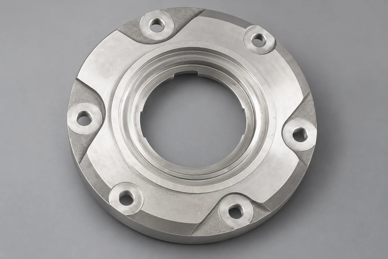
Send the Details for Your Component Review
Tell us what you need to buy and the condition you need to receive. Relia Casting will review the component, manufacturing scope and requested evidence with you before an order is agreed.
- Controlled carrier drawing
- Central profile and pin-interface details
- Datum and positional requirements
- Specified material and condition
- Inspection and application-trial requirements
No. 96 Shuyuan Road, Qingdao, Shandong, China
About our component supply · Contact details and project enquiry