
Shell-Mold Ductile Iron Hub Supports with Machined Mounting Features
A hub support is accepted by how its centre and arm-end contacts locate together. Relia reviews custom shell-mold ductile-iron supports with the grade, cast sections and machining scope defined. Use the assembly datum to agree stock and distributed mounting positions as one component.
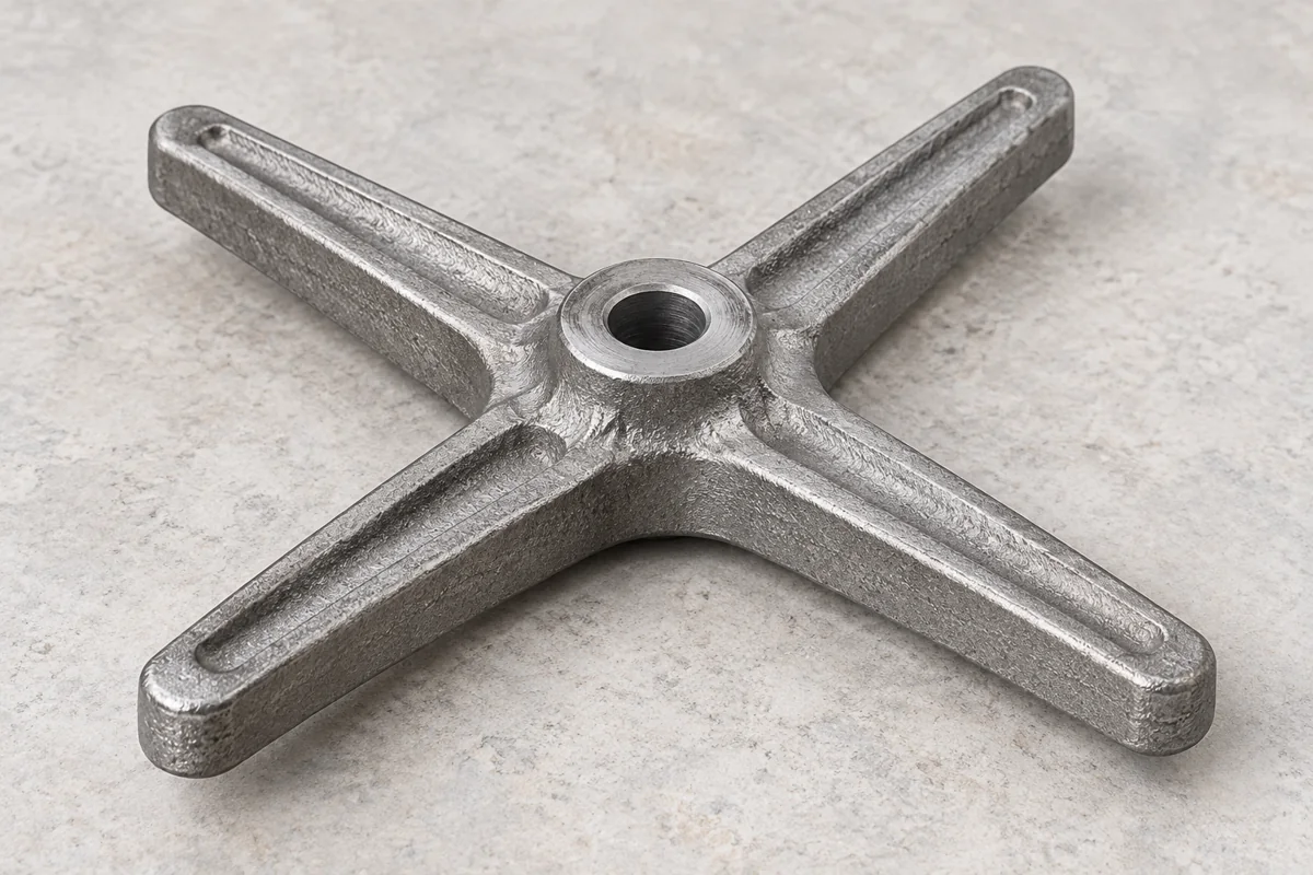
The Center and Arm Ends Define One Component
Relia reviews the support body, specified machining and inspection as one component scope. We distinguish the central hub, arm-end contacts and separately supplied hardware. This helps avoid a quotation that describes only an outside shape while leaving the finished mounting responsibility unclear.
Distributed Arm Interfaces Use a Common Reference
A multi-arm support has several interfaces around a common reference. Show how the central opening and outer contacts locate the assembly, including any mating parts. The hub-support and notched-plate catalogue forms are geometry references; they are not interchangeable drawings or proof of one standard assembly.
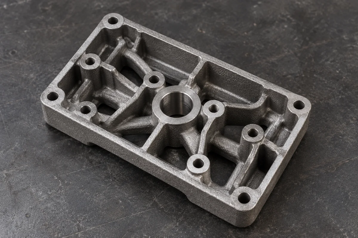
The Ductile Iron Grade and Condition Need Approval
Approve the actual ductile iron specification and delivered condition. Include the material evidence and application requirements relevant to the support. A grey- and ductile-iron option list does not establish which material a photographed casting uses or the load it can carry.
The Shell Route Reserves the Machined Features
The shell-moulding proposal considers the mould, any cores, section transitions and cleanup access. Clarify whether the route uses a shell mould or only shell cores within another moulding arrangement. Both the casting form and the stock required for finishing should be reviewed before tooling approval.
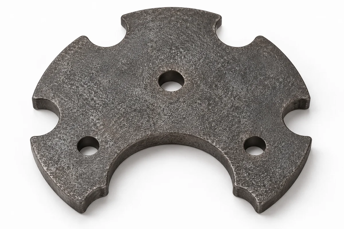
Machining Links the Bore to the Mounting Contacts
Relate the central bore and arm-end features to an agreed datum system. Specify the condition in which the support is held and measured. Distributed contacts need positional relationships, not only isolated diameters or hole sizes.
Cleanup and Treatment Protect the Working Contacts
Keep feed removal, parting-line cleanup and any treatment away from protected working contacts. Define the areas accepted as cast and those requiring finishing. Where coating is part of delivery, consider its effect on the final contacts and the sequence in which acceptance occurs.
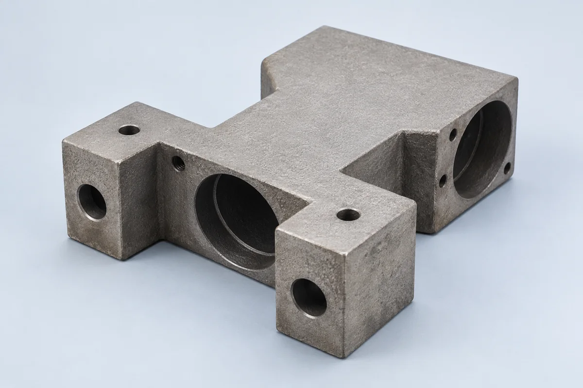
A Sample Checks the Distributed Mounting Geometry
A useful sample plan checks the central opening, the distributed mounting relationships and the selected material requirements. We can provide agreed key dimensional records for the order. Any assembly or load validation should have a separate method and acceptance basis rather than being inferred from the casting appearance.
The Quote Names Tooling, Finishing and Repeat Scope
Include the model, hub and arm-end requirements, material and quantities in the RFQ. Add tooling scope, sample checks, final condition and required records. This allows the shell-moulding proposal to be compared with the complete finished support in view.
Send the Hub Support and Mounting Drawing
Send the support drawing and assembly reference with the bore, arm ends and mounting datums marked. Add the approved ductile iron specification and quantities. We can review the moulding, machining and sample scope around those interfaces.
- [email protected]
- Phone
- +86 185 6176 2631
- +1 404 203 0971
- Project enquiry
- Contact our Qingdao team