
Shell-Mould Iron Castings for Flanges and Cylindrical Parts
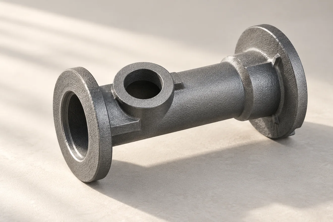
Relia can review shell-mould casting for repeated iron flanges and cylindrical parts using your actual grade, drawing and release quantities. The review distinguishes the complete outer mold from any shell core, then identifies cleanup and CNC work at the bore, end face or shoulder. The quotation therefore defines what the shell process supplies and which contacts arrive finished.
Read the overview and page sections
We compare the proposed route against your actual grade, drawing and release pattern, including machining stock and finished contacts. That gives your team a useful process decision rather than a broad promise of precision from the route name alone.
Repeated Demand Gives the Tooling Review Its Purpose
Relia connects the component's section layout with pattern reuse, core access and later CNC work. For repeated flange or cylindrical-part orders, Relia's proposal can separate tool development from recurring mold preparation and finishing. The required iron grade, cast clearances and machined interfaces remain distinct so your comparison covers the actual delivered part.
03 / 10Component decisions
Make the Shell-Mould Decision Part Specific
A route can improve repeatability while still needing cores, cleaning access and CNC finishing. Evaluate these requirements together.
| Design factor | Review for shell moulding | Purchasing implication |
|---|---|---|
| Parting and draft | Pattern withdrawal and divided geometry | Tool layout and allowed parting marks |
| Internal spaces | Core support and removal access | Cavity feasibility and cleanup scope |
| Cast tolerance | Defined dimensions and standard basis | No universal tolerance for every feature |
| Repeat demand | Tooling use across expected releases | Tooling cost, ownership and revision terms |
Cylindrical Features Need Defined Stock and Location
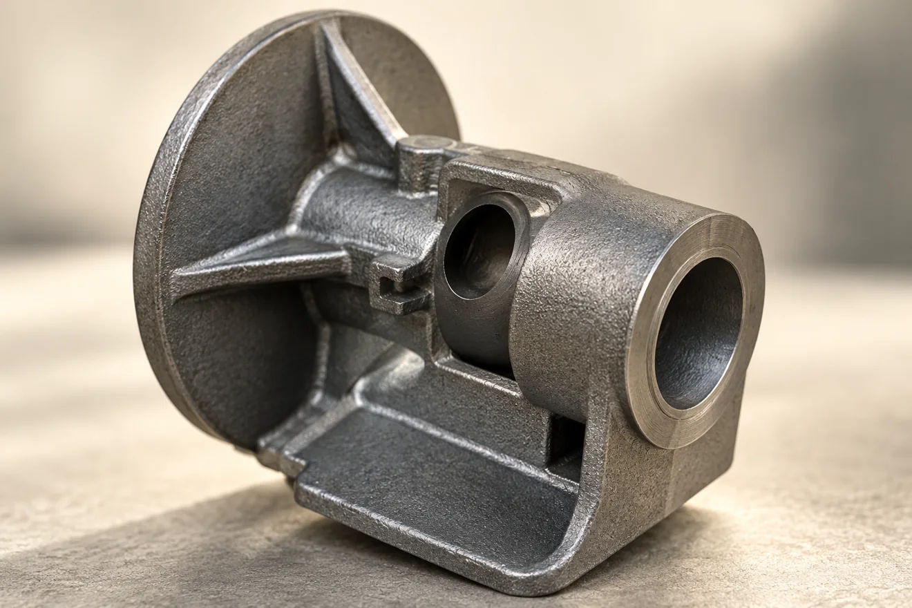
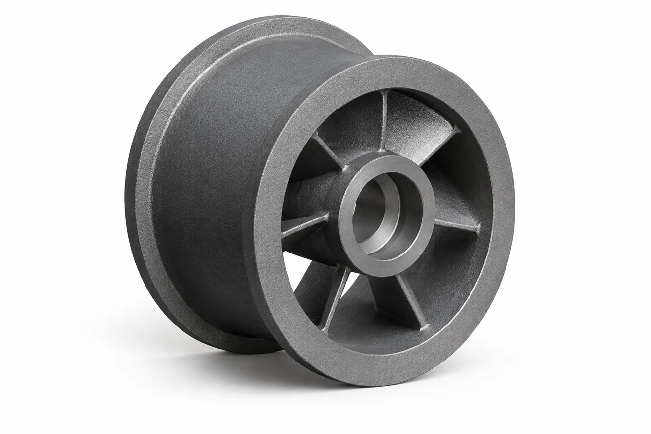
A flange or cylinder may require a finished bore, end face or shoulder. Mark those operations on the drawing and identify their datum relationship. Agree machining stock by feature so the casting supports the intended final geometry without relying on a general allowance applied to every surface.
Forms the external casting envelope. Review parting, draft and pattern withdrawal.
Forms an internal space. Review seating, support and removal access.
Link Pattern Approval with the Shell and Core Arrangement
In shell moulding, resin-bonded sand forms a rigid shell against a heated pattern.
- Pattern release
- Shell and cores
- Cleanup access
- Finished contacts
- Relate pattern approval to mold and core seating
- Prove the blank supports repeat machining
Open the manufacturing route and detailed review
Relate pattern approval to mold and core seating
The prepared mold sections and any required cores establish the casting cavity. Pattern parting, core seating and handling of the mold arrangement therefore need to suit the selected flange or cylindrical form before repeated production is planned.
Prove the blank supports repeat machining
Relia's review connects that tooling definition with the stock and locating areas needed by machining. The first accepted component is useful for checking whether the intended bores, faces and fixing features can be achieved from the shell-made blank. Later drawing changes should be related back to the pattern and machining references they affect.
Material and Cast Condition Have Separate Checks
State the required iron grade and any applicable material evidence. Separately define surface condition, flash, gate-removal and other blank-acceptance requirements that matter to your part. A sound-looking surface is not material verification, while a material record does not demonstrate that every cast feature meets the drawing.
07 / 10Component decisions
Keep Shell-Made Shape Separate from Machined Contact
The shell establishes the blank. Bores, seating faces or threaded connections may still need secondary operations to meet their own limits.
| Stage | Process focus | Acceptance output |
|---|---|---|
| Pattern | Define the reusable geometry and stock | Controlled pattern and blank reference |
| Shell and core | Form the mold and any internal features | Defined casting and cavity outline |
| Casting cleanup | Separate gates and remove residues | Agreed edge and surface condition |
| CNC and inspection | Finish and check functional contacts | Finished drawing and specified records |
Repeat Orders Keep the Tool and Part References Together
Repeat supply should identify the current part revision, tooling status and required release checks. Where a tool repair or process change affects accepted features, agree the relevant review before routine release. Batch records and packing identification then connect the delivered components to the accepted scope.
Send the Details for Your Component Review
Tell us what you need to buy and the condition you need to receive. Relia Casting will review the component, manufacturing scope and requested evidence with you before an order is agreed.
- Flange or cylinder drawing
- Specified iron grade
- Shell-mould route and tooling scope
- As-cast and machined requirements
- Sample approval and batch quantities
No. 96 Shuyuan Road, Qingdao, Shandong, China
About our component supply · Contact details and project enquiry