
01 / 10 · Part identity before production
Left- and Right-Hand Investment-Cast Mounting Parts
A mirrored mounting part needs its own technical reference. We help you define the two hands before casting and machining, so an apparently similar component does not reach the wrong position in your assembly.
Relia reviews the cast geometry, finished interfaces and requested identification together. The catalogue provides mounting and joint examples; your drawings establish whether the ordered parts are mirrored, identical or otherwise different.
Review your paired component drawings02 / 10 · Buyer and factory responsibilities
Paired Parts with Separate Technical References
Relia needs a controlled reference for each ordered component. Two similar images are not a reliable way to distinguish a handed pair, and the same photograph does not establish that two catalogue entries are interchangeable.
The assembly position, left/right naming convention, drawing revision, material requirement and quantity for each part.
The requested casting shape to machining references, permitted identification and the sample requirements for each drawing.
The pair as two controlled items, including any companion pins, screws or fittings that belong in the supplied scope.
03 / 10 · Assembly orientation
Mirrored Geometry and Assembly Orientation
Define left and right from a stated viewing direction or an assembly reference. A component turned over on a bench may appear to change sides while its actual hole pattern and contact faces remain the same.
Include an assembly view showing the mounting side, working direction and nearby clearances. For a hinge or clamp-style component, identify the moving and fixed members as well as the supplied cast piece. This avoids confusing a handed component with the other half of an assembly.
- Viewing directionName the drawing view used for left and right.
- Assembly positionShow the actual installed side.
- Mounting faceIdentify the locating contact.
- Working directionShow motion and required clearance.
04 / 10 · Casting definition
Pattern Identification Before Casting
A handed pair may need different pattern features or a different tooling arrangement. That decision follows the actual geometry; a mirror image should not be treated as proof that one tool produces both parts without a change.
Geometry to compare
Offset bosses, angled arms, slots, hole locations and the relationship of each feature to the mounting face.
Tooling scope to agree
The patterns or tool features required for each hand, their revision references and the samples needed to approve them.
The quotation should identify any shared and separate tooling responsibilities. Tooling cost and sample milestones are defined for the actual pair.
05 / 10 · Finished interfaces
Machining Setups for Each Hand
Compare the finished part drawings as well as the casting shapes. A pair can share a general outline while needing different bore directions, counterbores, threaded features or accessible clamping faces.
Mark the functional datums for each item. The machining proposal should preserve its own mounting relationship rather than borrow a convenient reference from the opposite hand. Any cast stock and fixture contacts also need to suit the selected component.
06 / 10 · Identification
Identification Marks on Permitted Surfaces
State the identification you need and where it may appear. A requested part reference must not interfere with a locating face, sealing contact, thin edge or visible surface that has a separate acceptance rule.
- DEFINEThe identifierAgree the part number, hand and revision information needed for the order.
- LOCATEThe permitted areaMark the surface or packaging location where identification is required.
- REVIEWThe proposed methodConfirm the feasible marking and packing scope in the quotation before production is released.
Separate component marking from packing identification
A part can need identification on its packaging without permitting a permanent mark on its surface. Define these requirements separately. Barcode formats, private branding or a particular marking process should be agreed explicitly rather than assumed.
07 / 10 · Sample approval
Separate Sample Approval for the Pair
Approve the left and right components against their own drawings. A successful check of one hand does not demonstrate that the other hand's offset, mounting pattern or machining direction is correct.
Relia can provide agreed key dimensional inspection records with an order, with the features and sampling frequency specified for that order. Record the reference used for each sample and the acceptance requirements for any assembled hardware.
08 / 10 · Catalogue references
Mounting and Joint Component References
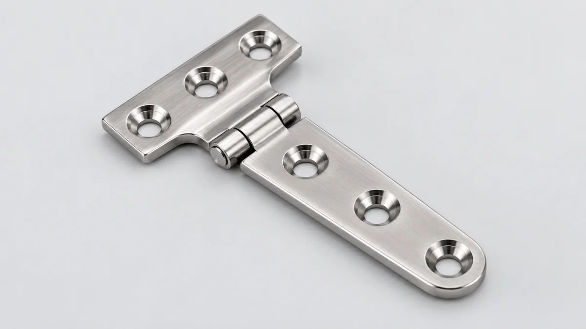
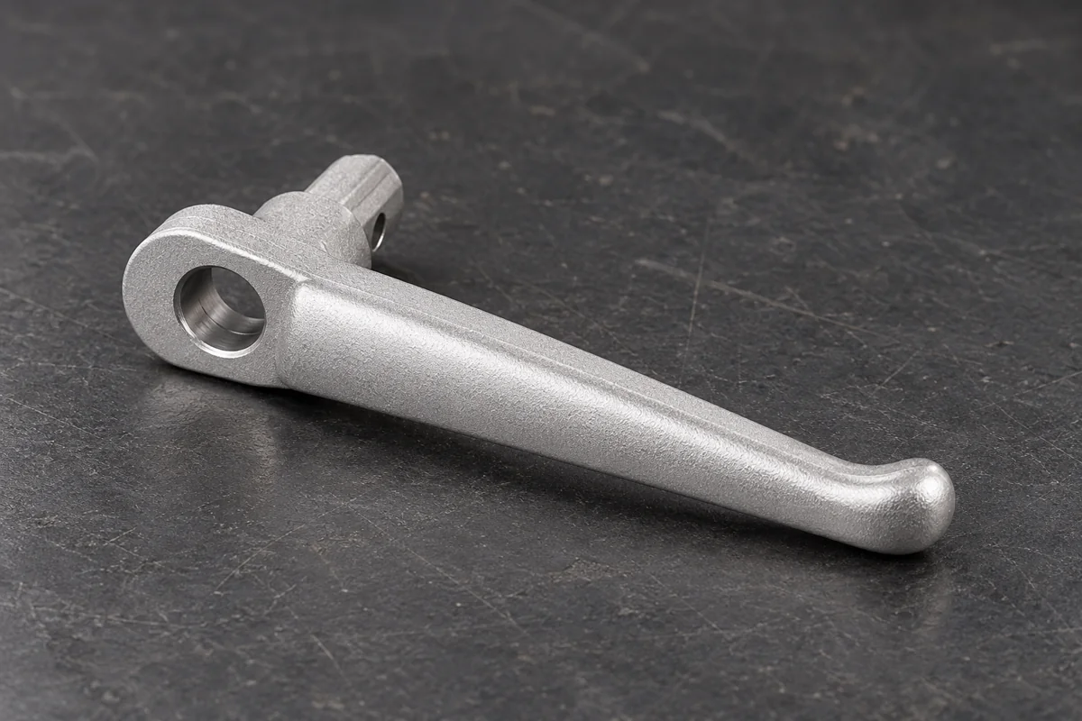
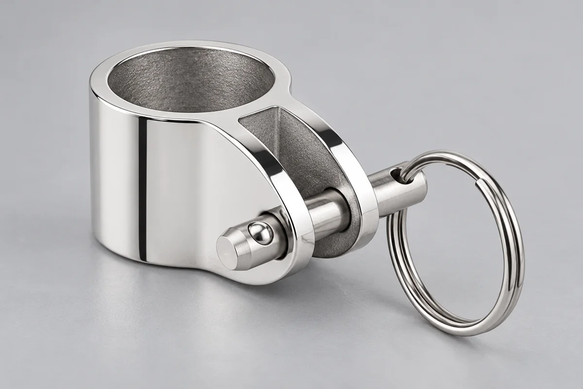
Use the catalogue to communicate the family of component you are sourcing. Relia lists hinge forms, clamp-style connections, mounting brackets, eye-ended levers and forked profiles for custom enquiries.
These examples have different geometry. They do not establish a complete handed kit, an approved load rating or a common material grade. Your drawing and quantity schedule define the actual items to quote.
View custom hinge and clamp casting componentsView mounting brackets and eye-ended lever examplesView slotted mounting parts and forked profilesReview the broader hinge and linkage component supply scope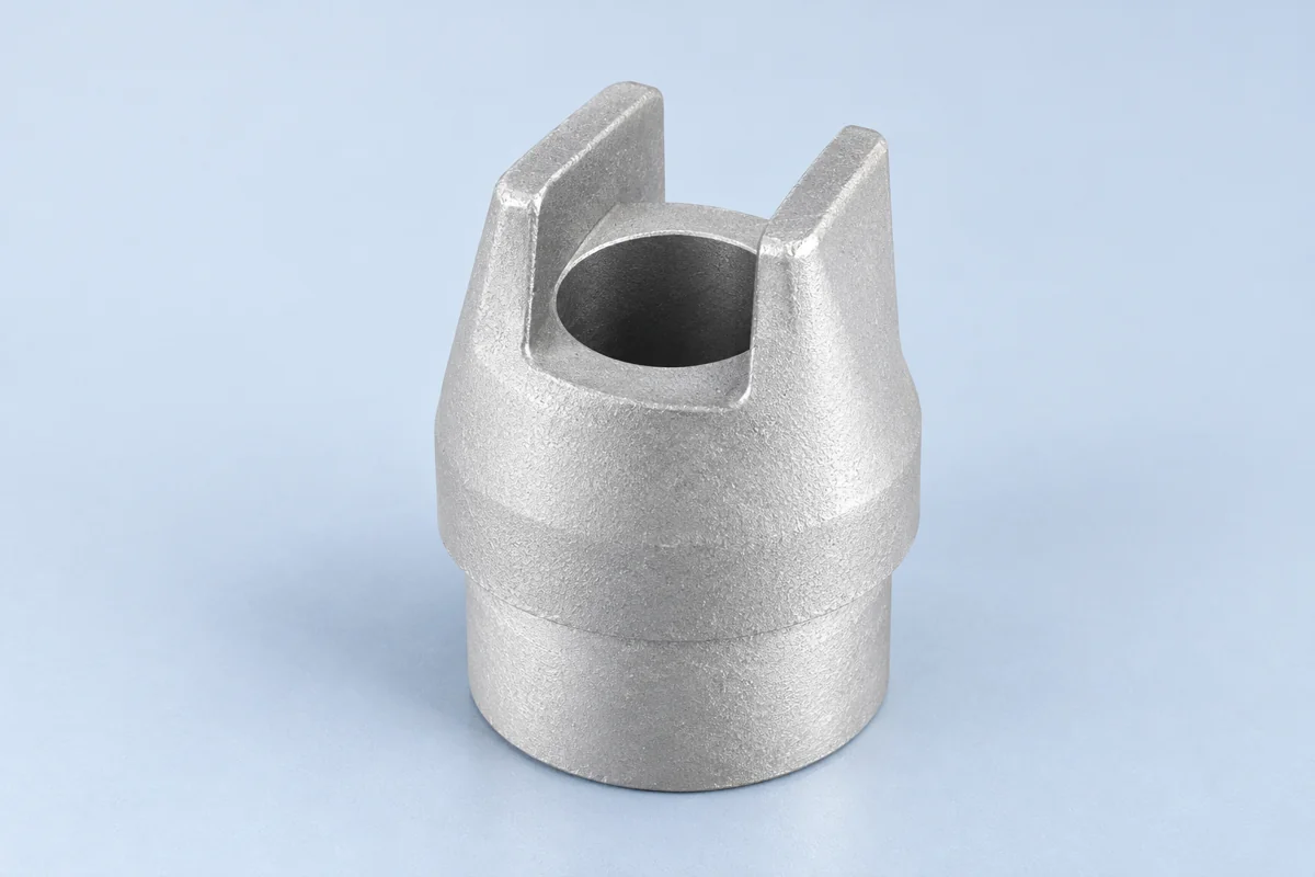
09 / 10 · Receiving the order
Part Counts and Packing Identification
Order each hand by its own part number and quantity. Do not rely on a total pair quantity when your stock, assembly line or service operation may need different counts of the two items.
List the drawing, revision and required quantity separately for each component.
Define the part references and separation needed for receiving. Agree any special labels or grouping before quotation acceptance.
Use the agreed identifiers and sample references to connect the delivered item to its assembly position.
10 / 10 · Start a paired-part review
Share Both Drawings and the Assembly View
Send Relia the two component drawings, material requirements and quantities. Add an assembly view that defines the hand, then mark the identification and sample evidence your receiving team needs.
We can review the casting and machining scope for each item and identify the points that need agreement before tooling or batch production.
Email the paired drawings- [email protected]
- Phone
- +86 185 6176 2631
- +1 404 203 0971
- Company and address
- Relia Casting
No. 96 Shuyuan Road
Qingdao, Shandong, China