
01 / 10 · A shared measurement definition
Shared Inspection Datums for Precision Casting Samples
Use the same datum references and support conditions when your team and the foundry compare sample measurements. A number is useful only when both teams know how the feature was located and checked.
Relia reviews the drawing, inspected characteristics and supplied condition before sample acceptance. We connect those requirements to a defined inspection setup so the discussion remains about the same component and the same measurement.
Review your inspection references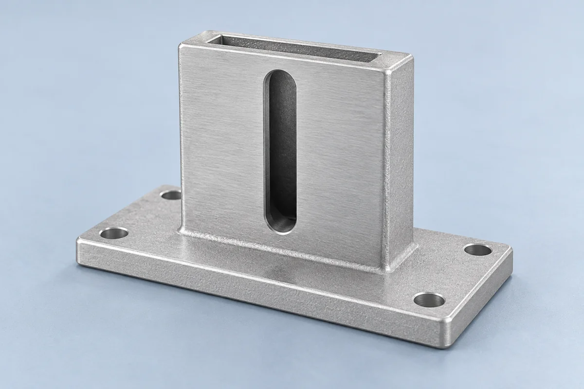
02 / 10 · Factory and quality team alignment
One Measurement Definition for Both Teams
Relia can provide agreed key dimensional inspection records with an order. Define the features, methods and sampling frequency for that order so the records answer your actual acceptance needs.
The functional drawing
Drawing revision, datum system, feature limits and the supplied condition to be accepted.
The inspection setup
Locating references, support or clamping, measurement method and required result format.
03 / 10 · Drawing interpretation
Functional Datums from the Assembly Drawing
Start with the references on the controlled drawing. Identify the surfaces or features used to locate the component in its working assembly, then agree how the inspection will establish those references.
04 / 10 · Physical setup
Support and Clamping During Inspection
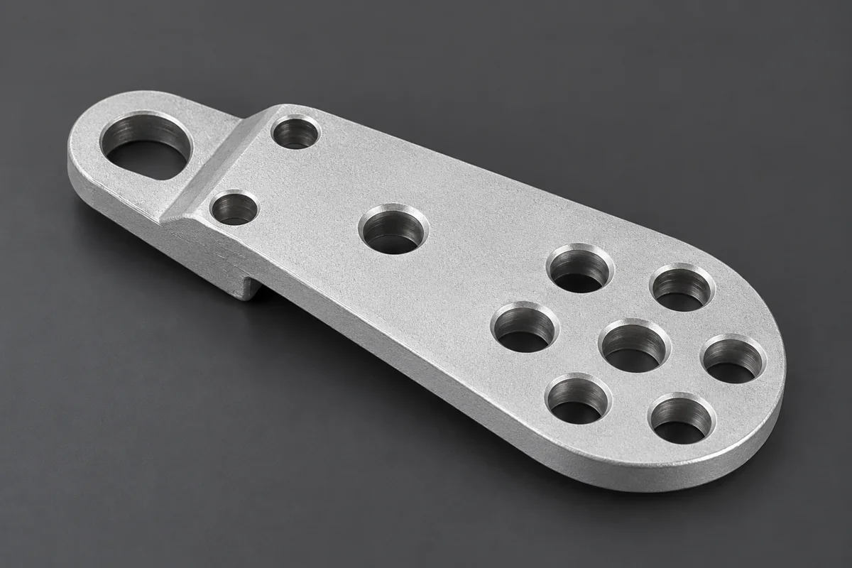
State where the component is supported and whether it is measured free or restrained. Contact positions and clamping can matter when comparing a slender arm, broad plate or thin-wall feature.
Location
Show the features that establish position and orientation in the inspection setup.
Support
Define the supporting and clamping contacts relevant to the required measurement.
Describe the setup with the measurement record
A sketch or setup photograph can make the agreed contacts clear. Identify the component revision and the supplied condition. Any constraint used for inspection should follow the approved drawing and acceptance agreement.
05 / 10 · Supplied condition
Cast and Machined Features in the Setup
Separate the casting blank from the finished component. A cast reference used to locate the first machining operation may not be the reference used to accept the final flange, bore or hole pattern.
Identify the stage of each recorded measurement and keep it connected to the appropriate drawing. Include treatment or finishing condition where it affects the acceptance definition.
Separate as-cast and machined tolerance requirements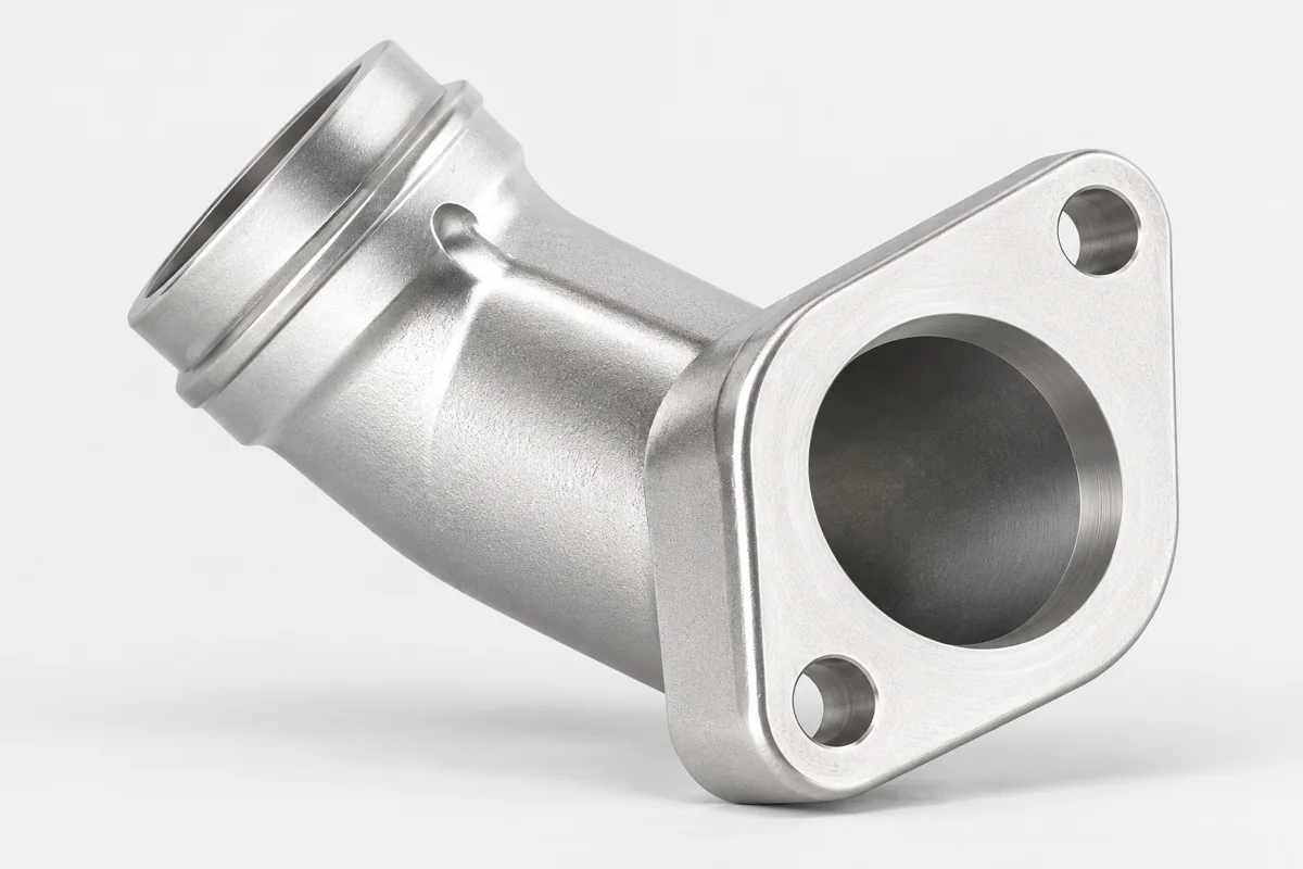
06 / 10 · Measurement method
Measurement Method and Environmental Conditions
Agree how each important feature is checked. A gauge, a direct dimensional measurement and a coordinate-based inspection may provide different information, so choose the method against the specified characteristic.
- Physical setup
- Locating surfaces, support and any clamping.
- Method and conditions
- Instrument or gauge approach and relevant environment.
- Result identity
- Units, sample reference, supplied state and presentation.
Record the setup with the result. If readings differ, compare these fields before deciding that the part has changed.
07 / 10 · Sample comparison
First-Sample Results Compared Feature by Feature
Compare the same identified sample in the same defined condition. If results differ, review the references and setup before drawing a conclusion about the casting.
- REFERENCEMatch the drawingConfirm revision, feature definition and datum interpretation.
- SETUPMatch the physical contactsReview support, clamping and the method used for the feature.
- RESULTResolve the actual differenceCompare recorded values and agree any further measurement needed.
Agree any required measurement uncertainty or laboratory documentation in the inspection scope before sample acceptance.
08 / 10 · Component references
Mounting and Bored Component References
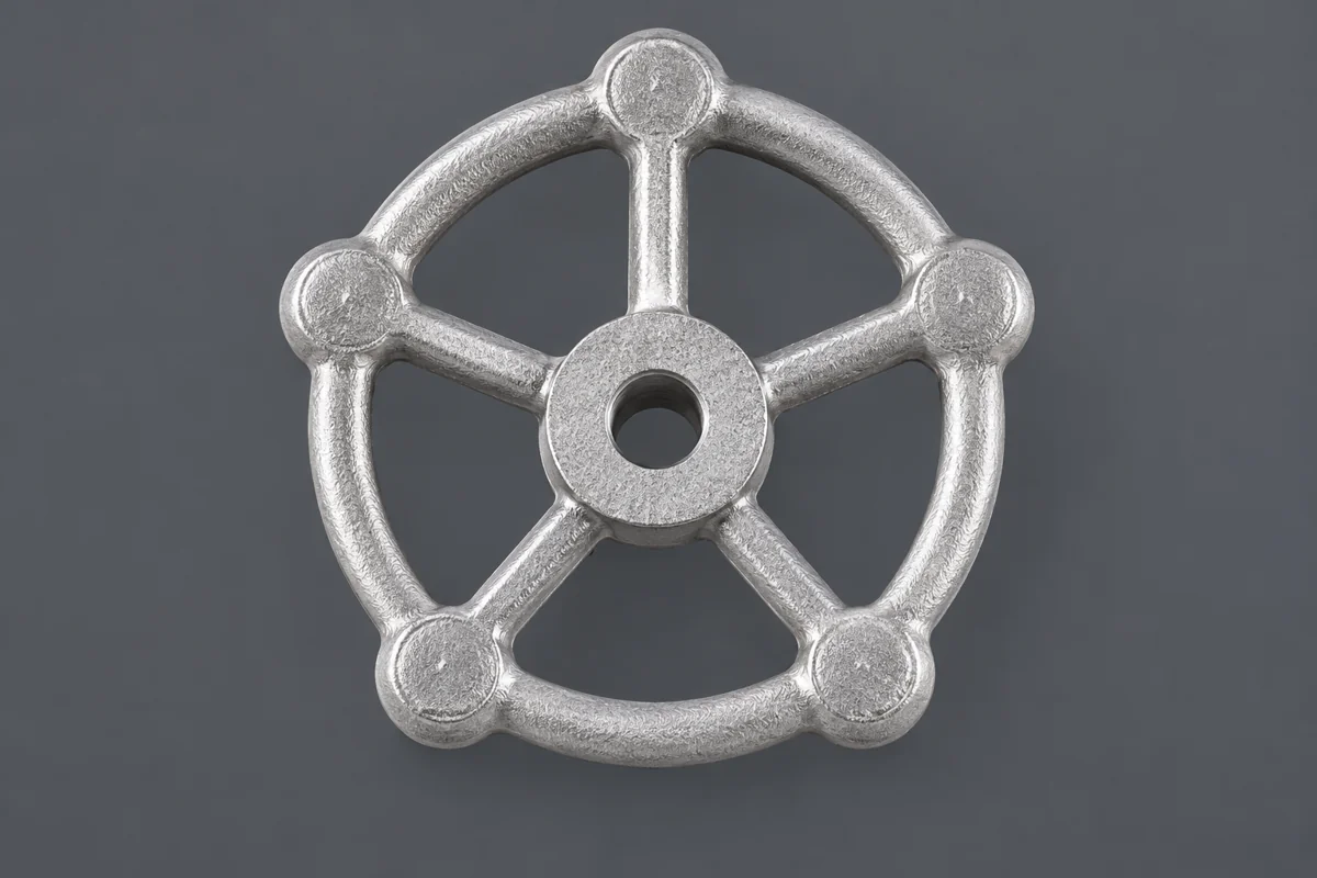
Relia's catalogue includes slotted mounts, eye-ended plates, bored profiles and flanged components. Their inspection requirements come from the selected drawing and assembly, rather than the general precision label.
View slotted mounts and bored component enquiriesView mounting plates and lever geometry referencesReview component inspection and acceptance planningReview a separate bore-to-face alignment enquiry09 / 10 · Production release
Resolve Differences Before Production Approval
Keep the agreed setup with the approved drawing and sample requirements. It gives both teams a common reference for the order and for reviewing any later design change.
Sample release
Customer approval follows agreement of the drawing, acceptance requirements and required sample evidence.
Repeat production
Retain the agreed feature and method definitions; set production inspection frequency for the actual order.
10 / 10 · Connect the quality teams
Share the Drawing and Your Inspection Setup
Send Relia the controlled drawing, critical feature list and any existing setup sketch or sample measurement comparison. Include the material and delivered condition you need.
Email your inspection requirements- [email protected]
- Phone
- +86 185 6176 2631
- +1 404 203 0971
- Company and address
- Relia Casting
No. 96 Shuyuan Road
Qingdao, Shandong, China