
Compare Aluminium Casting Routes for One Finished Part
Compare aluminium casting proposals against one finished housing, one alloy requirement and one quantity basis. Relia can review how internal access, wall layout and subsequent machining affect the alternatives. Use this guide to connect route choice with the final part your assembly needs.
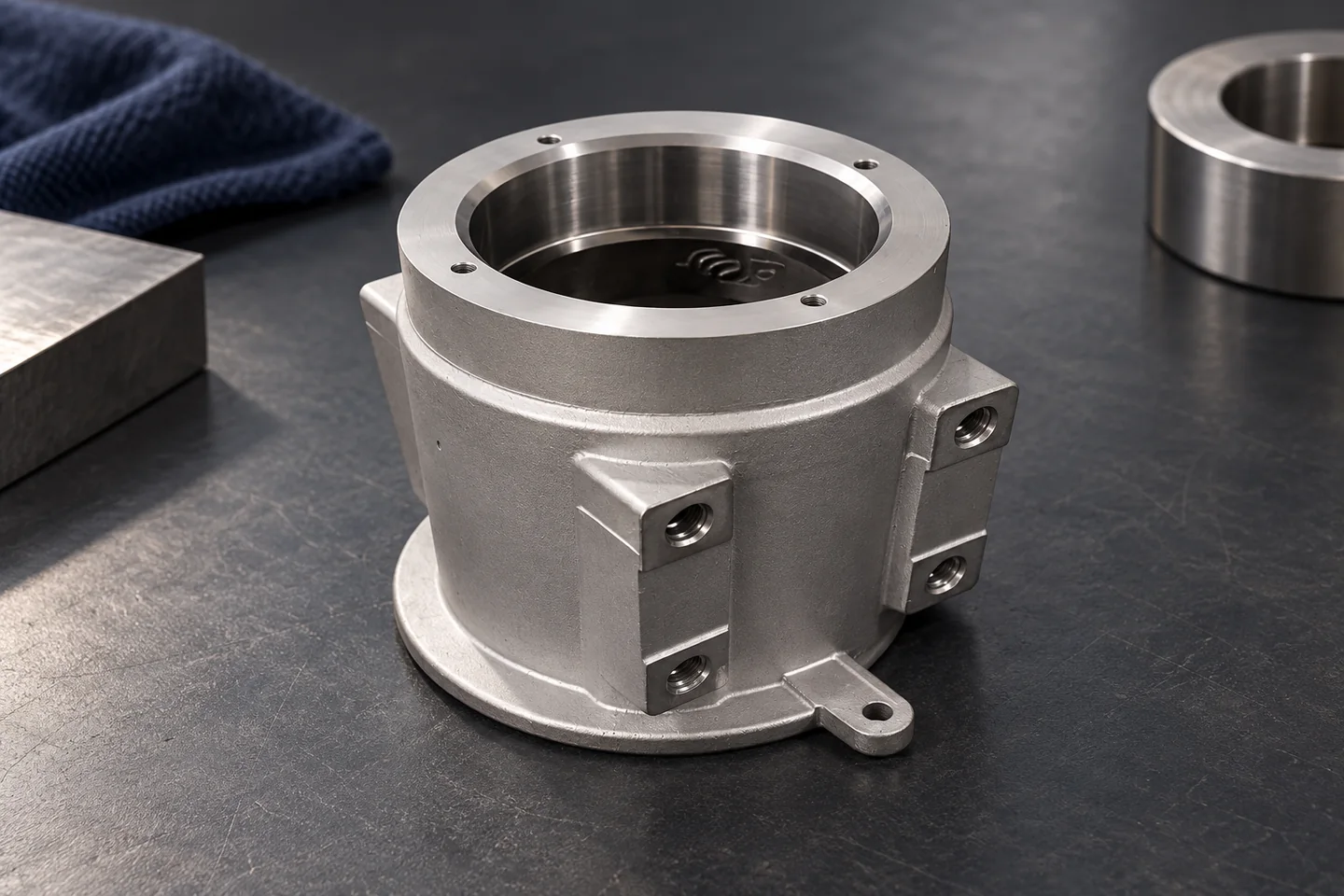
- Keep constant
- Drawing and final supplied condition
- Compare explicitly
- Alloy, mold or die, quantity and secondary work
- Review risk
- Internal geometry, soundness and finished fit
Use a Material Specification That Matches the Product Form
Relia connects each aluminium proposal to the interfaces on the finished component. A deep passage may change the mold solution, while a repeated thin-walled form can change the tooling discussion. Relia needs the selected alloy, demand pattern and important machined contacts to assess those tradeoffs. Any pressure or leak requirement should be stated before assuming that similar exterior geometry makes the routes equivalent.
Cast component
Specified casting alloy and supplied condition
Wrought alternative
A distinct product form and material proposal
Engineering decision
The approved material and manufacturing combination
Mounting Features Shape the Finished-Part Requirement
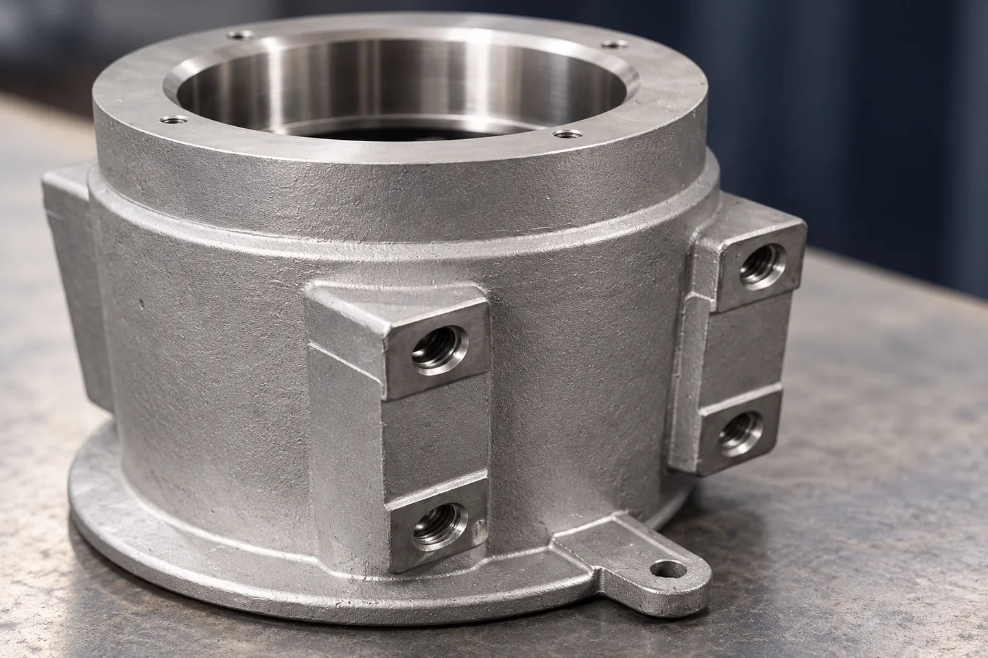
A housing's overall envelope may be simple while its flange, bore and side lugs control assembly. Mark those interfaces and explain the mating conditions. We use them to focus the route and machining discussion on the part your team must fit, rather than on the outside shape alone.
Compare Routes with One Geometry and Quantity Basis
Different casting routes can lead to different tooling and subsequent operations. We review those consequences against the same component requirement. The useful comparison explains the proposed route, its assumptions and any features needing further review instead of claiming that one process is always the least costly.
Geometry
Openings, section relationships and fixed interfaces
Tooling and quantity
Development scope and order stages
Finished condition
Machining, surface work and acceptance
Trace Each Alternative Through to Final Acceptance
A fair comparison shows the operations after the blank is made. Tooling, cleaning, machining and testing may differ even when the final drawing is unchanged.
- 01Route choice
- 02Blank production
- 03Secondary work
- 04Sample evidence
| Production stage | Operation and purpose | Control to agree |
|---|---|---|
| Route choice | Review sand, permanent-mold gravity or pressure-die proposals. | Alloy suitability, internal access and demand pattern. |
| Blank production | Describe filling, feeding or venting for the selected route. | Wall transitions and the relevant soundness risks. |
| Secondary work | Include trimming, treatment where specified and CNC finishing. | Final contacts, cut depth and finishing allowance. |
| Sample evidence | Assess the supplied part in the required final state. | Dimensions and separately defined material or leak checks. |
Show the Adjustable Features Before Tooling
Tell us where the design allows changes and where the geometry is fixed by an assembly. We can then discuss proposals without moving an essential interface. Keeping that distinction visible early makes a route review more productive than changing the drawing only after tooling assumptions have been made.
Surface Condition Needs an Area-Specific Requirement
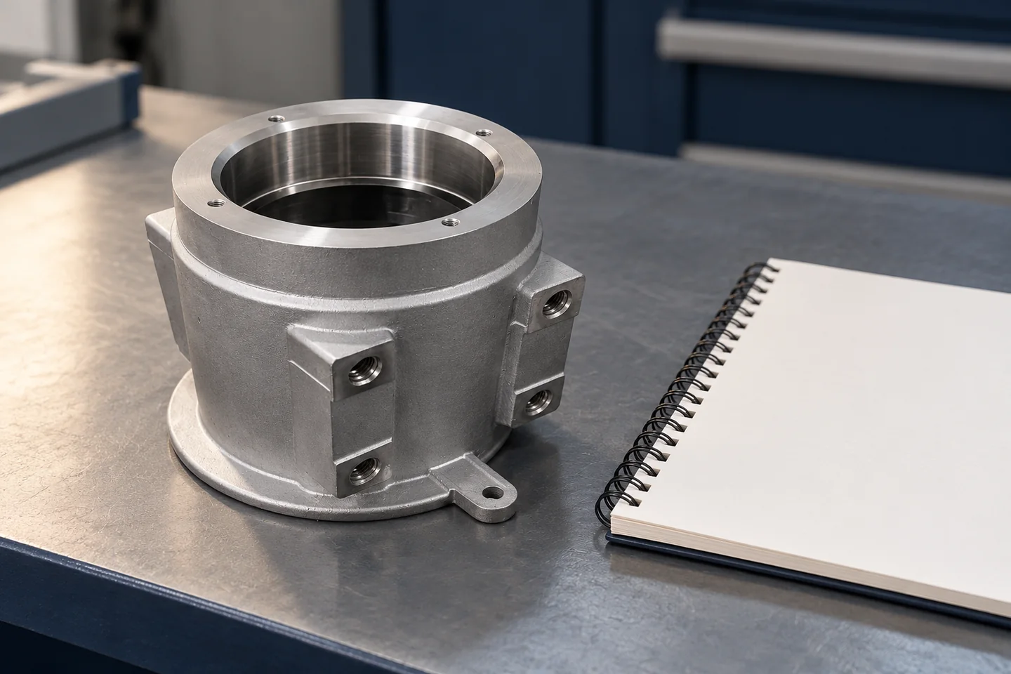
Appearance, protection and a working contact surface may need different acceptance decisions. Identify the relevant areas and required finish. We discuss the actual scope with the component proposal so a general finish description does not leave critical interfaces undefined.
Visible area
Appearance reference and finish scope
Working interface
Fit and contact-surface requirements
Delivery condition
Cleaning and protection agreed for receipt
Keep Soundness and Fit as Separate Checks
A component that assembles correctly may still need material or internal-quality evidence. Tell us the acceptance requirements relevant to your application. We agree the applicable checks and records rather than treating dimensions, appearance and service performance as one interchangeable result.
Geometry
Critical sizes and feature relationships
Material
Specified alloy and supplied-condition evidence
Service risk
Applicable functional or internal-quality checks
Review the Sample in the Intended Supplied Condition
The sample should show your team the interfaces and surface condition that the proposal includes. We align the requested evidence with that review. Any unresolved point remains visible against the drawing before a production or repeat-order decision is made.
Bring the Route Comparison Back to Your Drawing
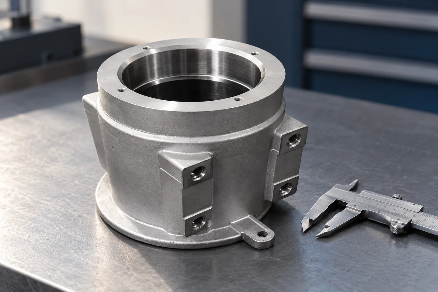
Send the cast alloy, drawing revision, quantity stages and required finished condition. Identify the interfaces and evidence that determine acceptance. We can then focus the proposal on the actual component and explain the route-related assumptions that need your review.
A useful first message
- Finished housing drawing and alloy
- Internal geometry and essential interfaces
- Sample, order and repeat quantities
- Required finish and acceptance evidence
The email link opens an editable draft. Share the information you have and identify any open points.
Relia Casting · Project Contact[email protected]Phone: +86 185 6176 2631WhatsApp: +1 404 203 0971Qingdao office: No. 96 Shuyuan Road, Qingdao, Shandong, ChinaRelia Casting homeMore relevant component and technical pages
Product illustrations explain catalogue-based geometry. The agreed drawing, material specification and order define the supplied component. Manufacturing and project acceptance requirements are reviewed for the actual part.