
01 / 10 · Bosses, arms and their junctions
Investment Casting Review for Thick-to-Thin Junctions
If you are sourcing an investment-cast mounting part with a heavy boss and a slender arm, review their junction before releasing tooling. Relia connects the cast blank to the finished bore or mounting face, so filling, solidification and machining stock are reviewed together.
Section relationships shown schematically; no dimensional recommendation is implied.
Relia reviews the actual sections and working interfaces before proposing tooling and samples. Your assembly requirements remain the basis for any geometry change.
Review your section junctions02 / 10 · Factory feasibility review
Geometry Review Before a Production Commitment
Relia connects the component drawing to the casting and finishing proposal. We review thick sections, thin regions and the transitions between them instead of treating a minimum wall value as the complete design requirement.
Your functional limits
Assembly envelope, loads, contact locations and dimensions that must remain controlled.
The manufacturing proposal
Cast geometry, proposed feed and cleanup regions, machining stock and sample evidence.
03 / 10 · Geometry input
A Section Map of Bosses and Arms
Provide section views through the boss, the arm and their junction. Show local thicknesses, internal holes and the finished surfaces reserved for machining.
Mark clearance limits and protected mounting dimensions so proposed transitions can be evaluated against the actual assembly.
Review separate thin-section housing and deep-recess requirements04 / 10 · Casting mechanism
Transitions that Influence Filling and Solidification
Thin regions can lose heat quickly during filling, while heavier local sections can remain hot for longer. Abrupt changes therefore need review with the proposed casting orientation and feeding arrangement.
Consider the connected flow path and local section geometry.
Consider how the local hot region is fed as metal solidifies.
Approve any proposed blend or section change before modifying the drawing.
Agree feasibility for the actual geometry and alloy
Useful section limits depend on the component, selected material and process proposal. A catalogue photo or a general wall-thickness claim does not establish the acceptance of a new design.
05 / 10 · Feeding and finishing
Feed and Cleanup Zones to Review
Identify locations where the proposed feed system meets the component and how those areas will be separated and finished. Keep removal and cleanup clear of protected mounting faces, edges and thin sections.
Review the expected supplied condition at the junction, with any local surface or additional inspection requirements specified in the order.
06 / 10 · CNC envelope
Machining Stock Around the Junction
Show the final boss bore, mounting face or fixing pattern over the proposed casting. Define the local stock and locating references needed for the agreed machining operations.
Cast section
The proposed blank must contain the material needed for the finished geometry.
Finished interface
The drawing establishes the required dimensions, relationships and supplied condition.
07 / 10 · Sample evaluation
Sample Evaluation at the Selected Locations
Agree which junctions and related interfaces need evaluation. Specify dimensional checks, surface observations and any additional testing with its method, coverage and acceptance criteria.
Relia performs agreed nondestructive testing in its own factory. The selected scope belongs to the actual order; it is not a blanket claim that every component receives the same examination.
Define NDT zones and acceptance requirements for the casting enquiry08 / 10 · Component references
Mounting Component Geometry References
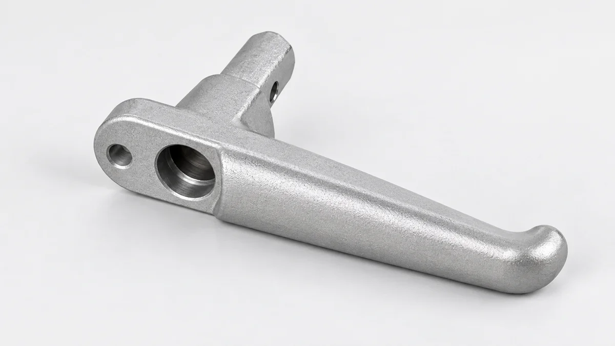
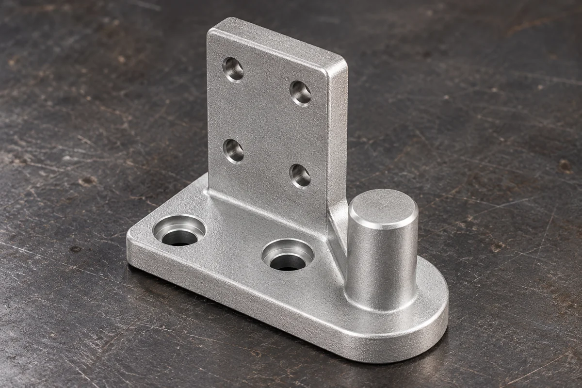
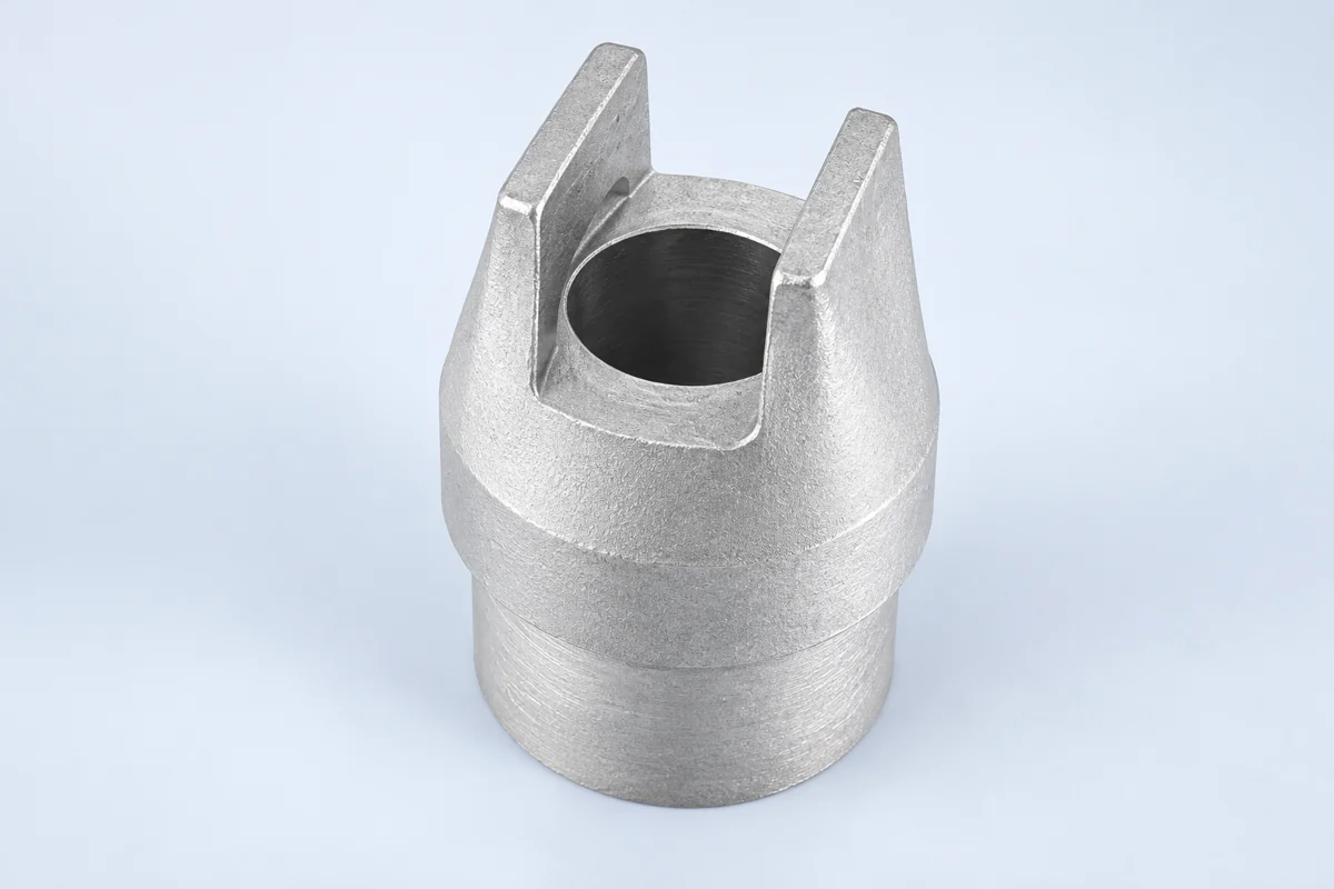
Levers, brackets, fork ends and hubbed forms provide different examples of connected thick and thin regions. Match the selected form to your drawing before agreeing the casting proposal.
View lever and mounting-bracket casting enquiriesView fork ends and hubbed precision-casting forms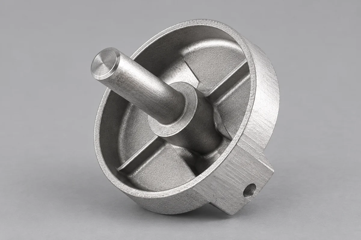
09 / 10 · Release decision
Approve Geometry and Evidence Together
Include approved transitions, stock and protected interfaces.
Connect the observations and records to the drawing revision.
Obtain customer approval before arranging the batch.
Key dimensional records and sampling frequency can be agreed per order.
10 / 10 · Start a geometry review
Share Sections and Critical Mounting Dimensions
Send Relia the component drawing, selected alloy and quantities. Include sections through the heavy boss and thin arm, along with the assembly dimensions that must remain protected.
Email the section drawing- [email protected]
- Phone
- +86 185 6176 2631
- +1 404 203 0971
- Company and address
- Relia Casting
No. 96 Shuyuan Road
Qingdao, Shandong, China