Custom Stainless Steel Sheet Metal Bending and Stamping Brackets | Curved Mounting Parts
-
Model Number2206MaterialAluminum
-
ApplicationElectronicsDimensionsCustomer Required
-
Surface treatmentPaint/Powder coating/oxidation etcMold makingBy ourself
-
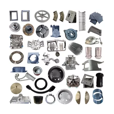
ProcessDie Casting-deburring- MachineryServiceOEM ODM
-
FeatureEco FriendlyQuality ControlProfessional Inspection
-
PackingCarton
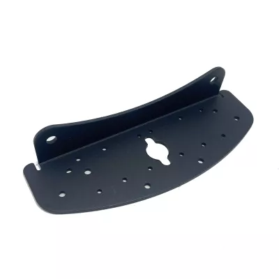
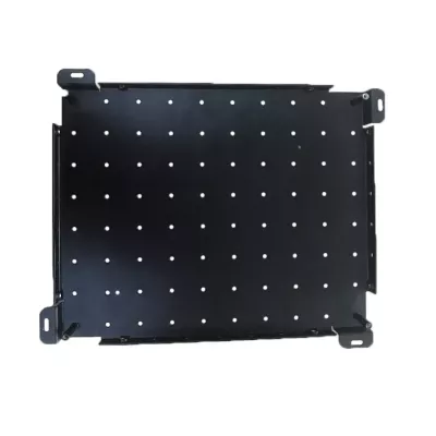
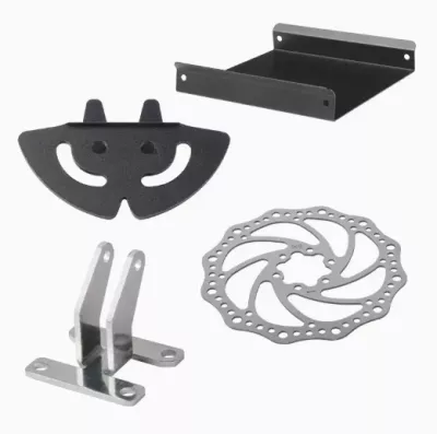
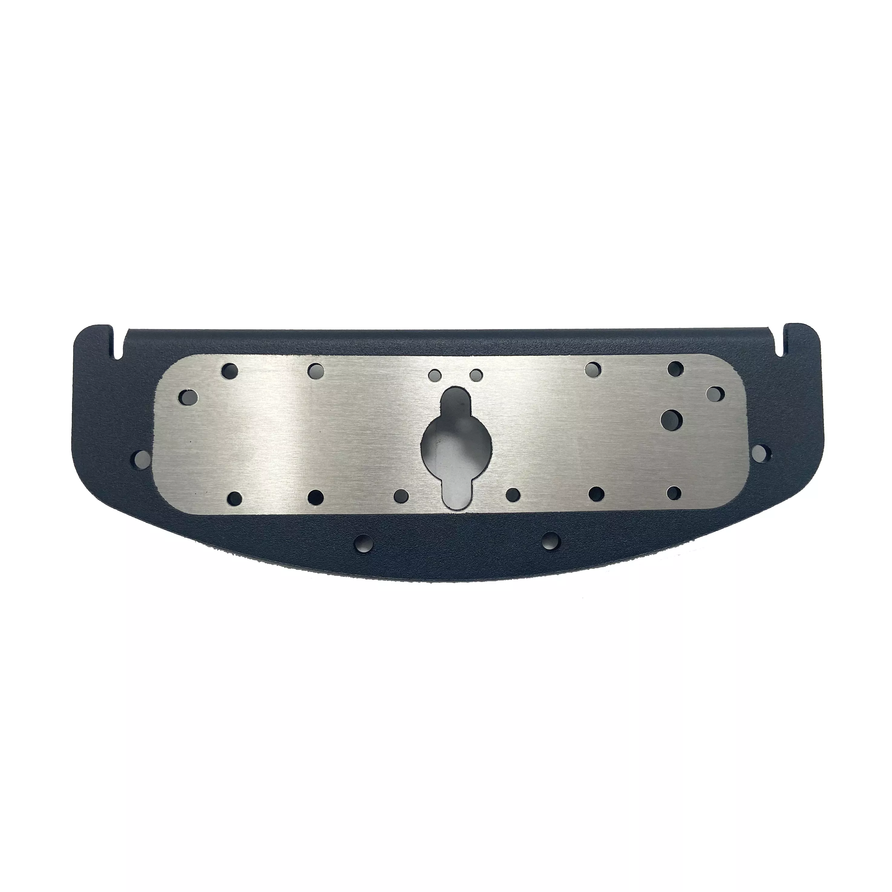
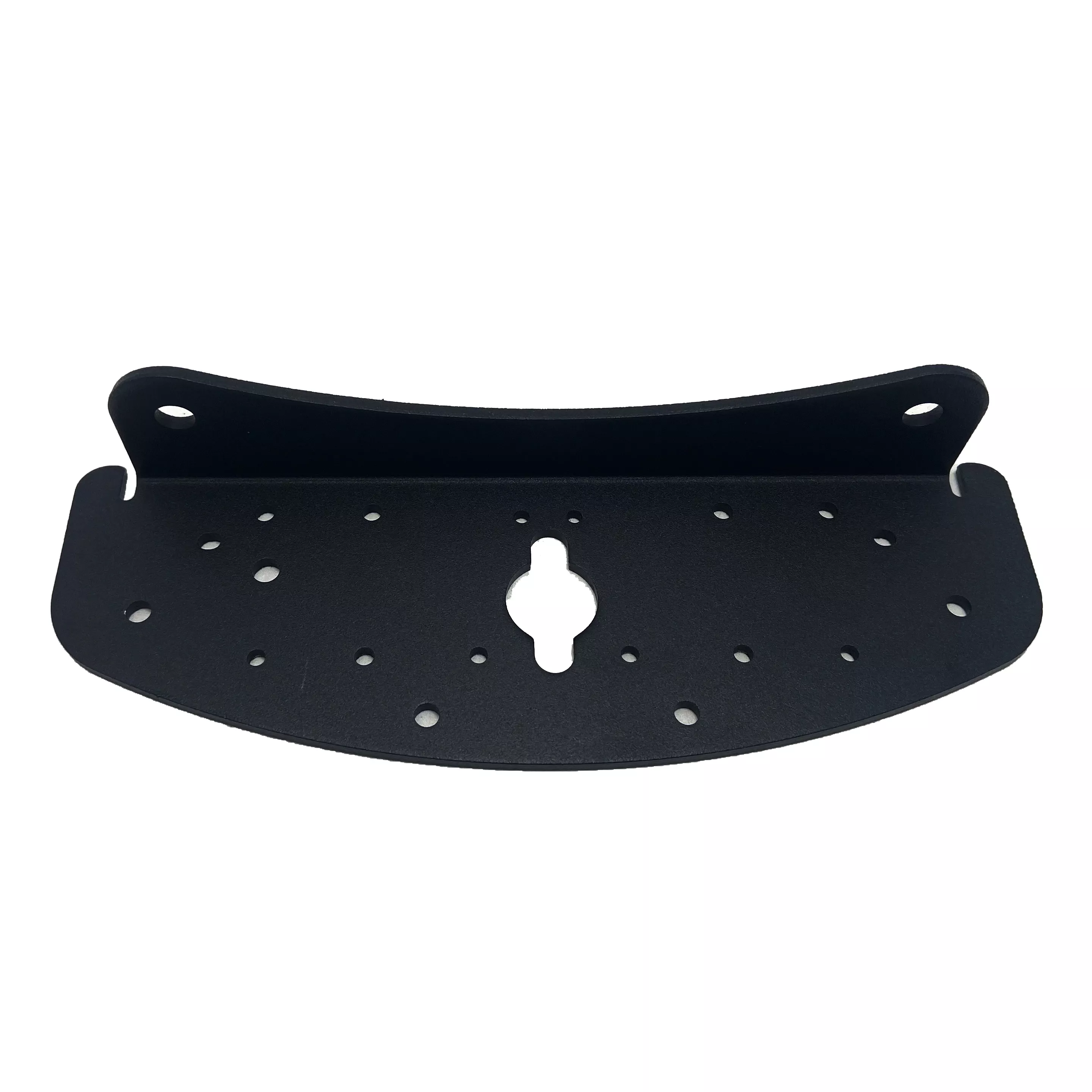
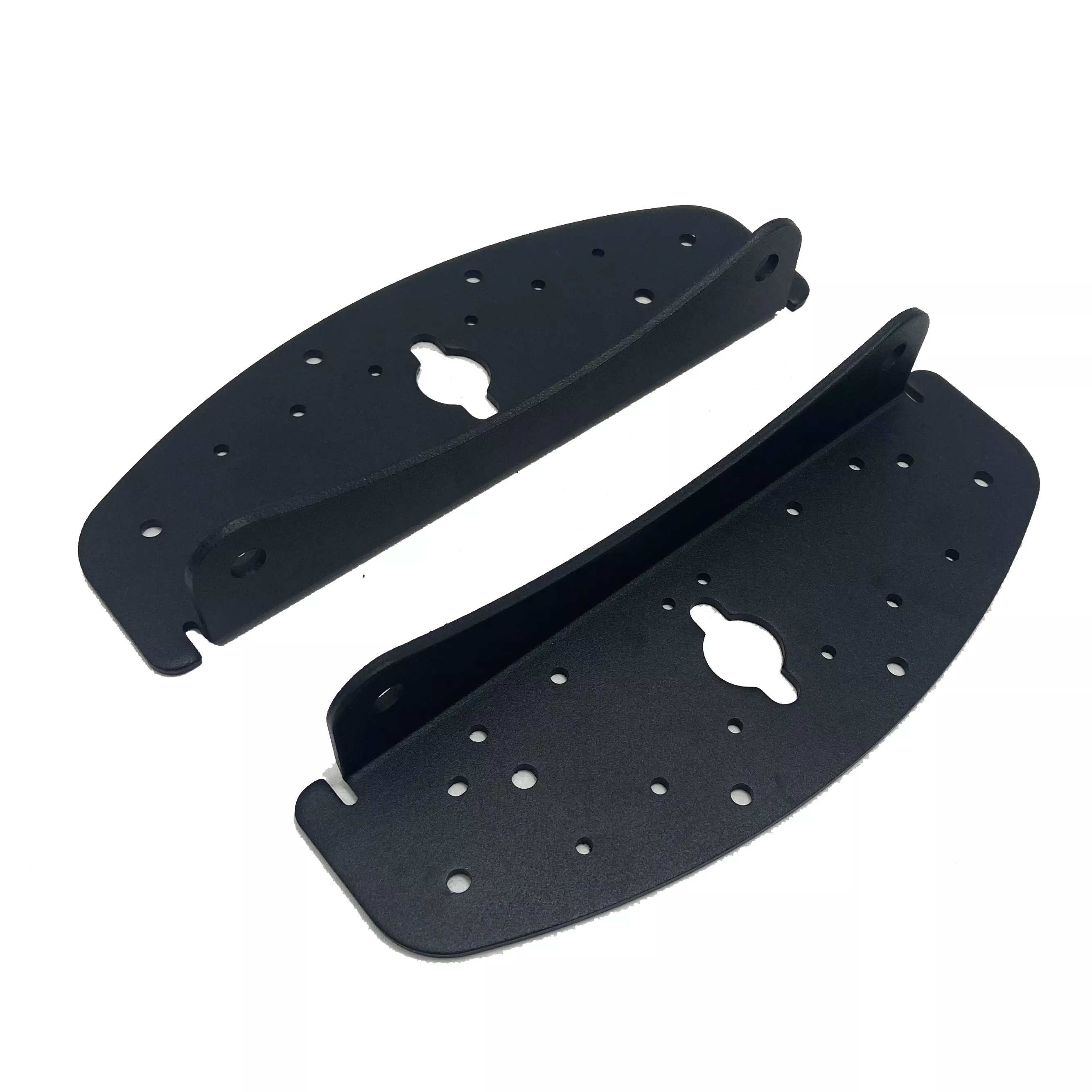
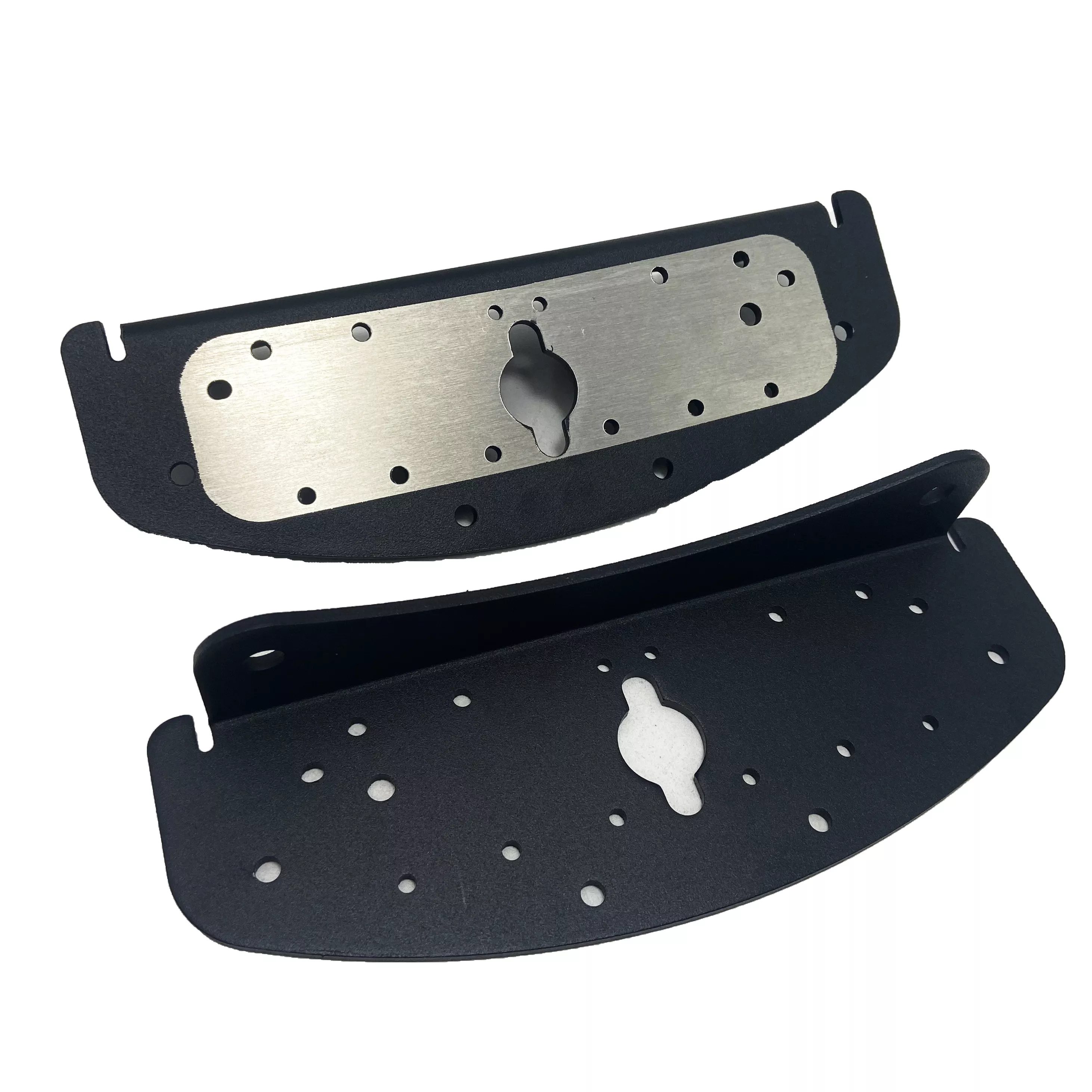
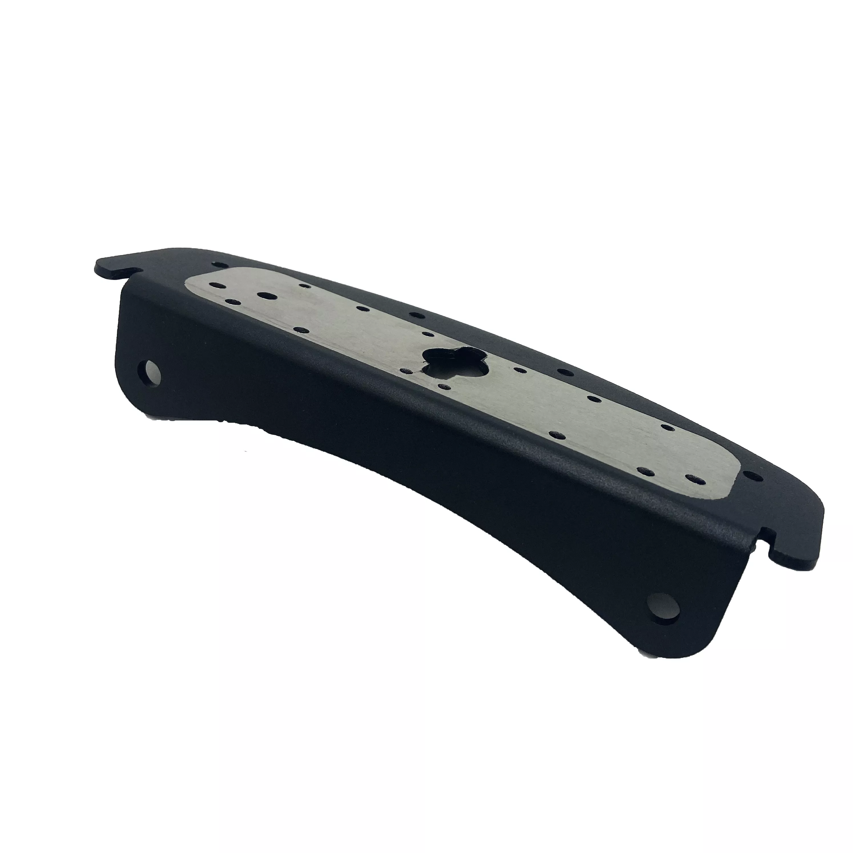
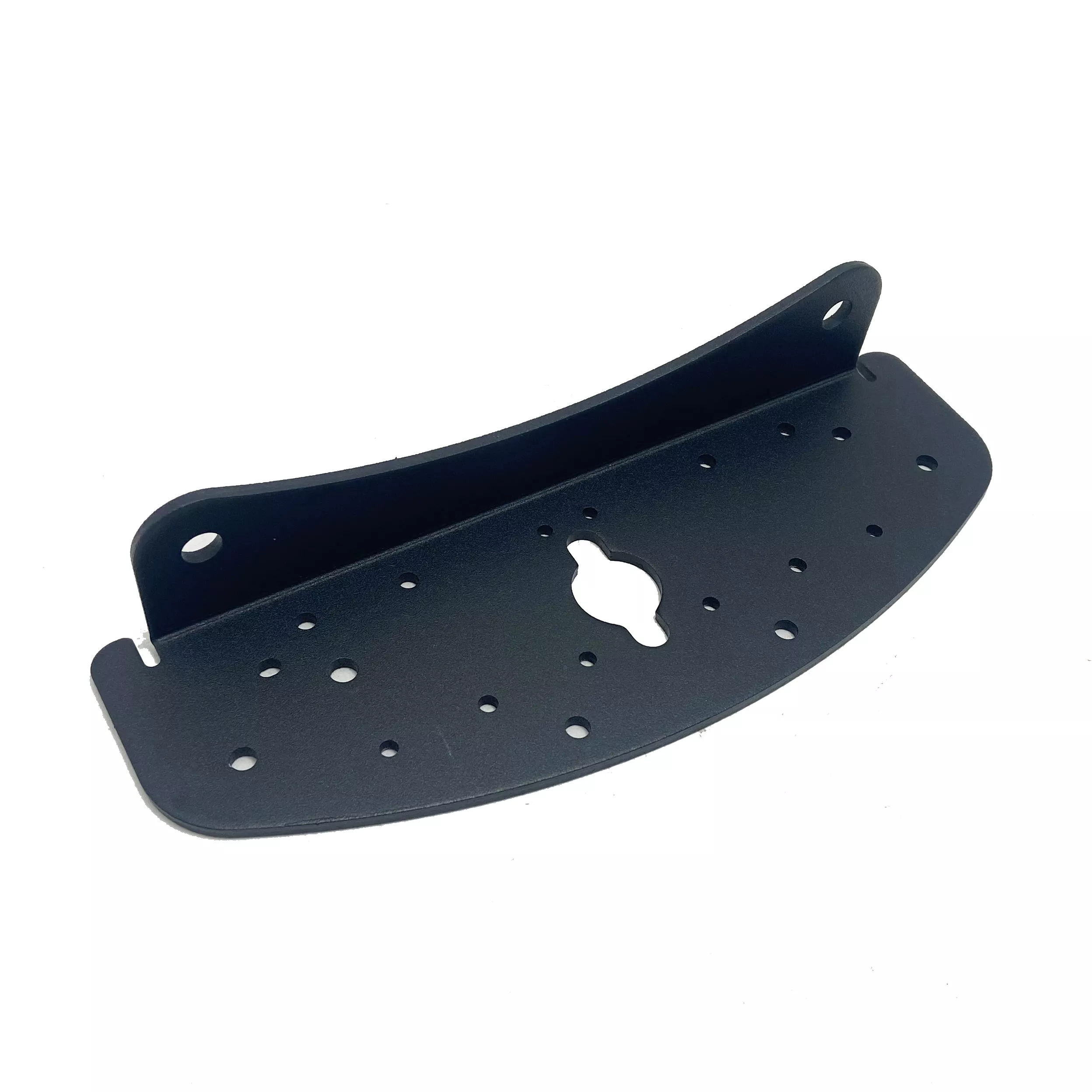
Define the curved bracket through its raised rear flange, end fixing holes and shaped central cutout. The dark example also has many smaller holes across the base. Its appearance does not establish stainless steel composition, sheet thickness, allowable loading or a particular manufacturing route.
Locate the curved base and raised flange together
Provide flat and formed geometry with actual bend or forming relationships. Reference the larger end holes, smaller openings and central cutout to assembly datums. Identify adjoining parts and contact or clearance requirements, including any hardware or inserts supplied with the bracket.
- Reference the curved bracket and mating assembly.
- Choose actual stainless grade and sheet thickness.
- Dimension holes, cutout and raised-flange relationships.
- Define cutting, stamping, forming and compatible finish.
- Agree curved-bracket inspection and mounting acceptance evidence.
Select the metal and sheet-fabrication route
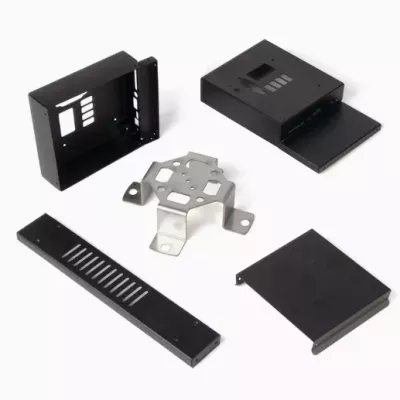
Stainless steel is the title's material direction; aluminum or another requested metal requires a separate grade and condition specification. Define cutting or stamping, bending or forming and any secondary edge work for the actual design. A general process entry does not establish how this particular curved sheet component must be made.
Accept the mounting interfaces in final condition
Mark tolerances with units and final measurement conditions at the working contacts. Select a compatible coating or appearance requirement where needed. Any load, electrical or environmental requirement needs actual operating conditions and applicable tests; dark finish and bracket shape do not prove those results.
Include quantities, controlled drawings and required material or inspection records. Keep the component scope explicit so proposals for different alloys or forming plans remain comparable.