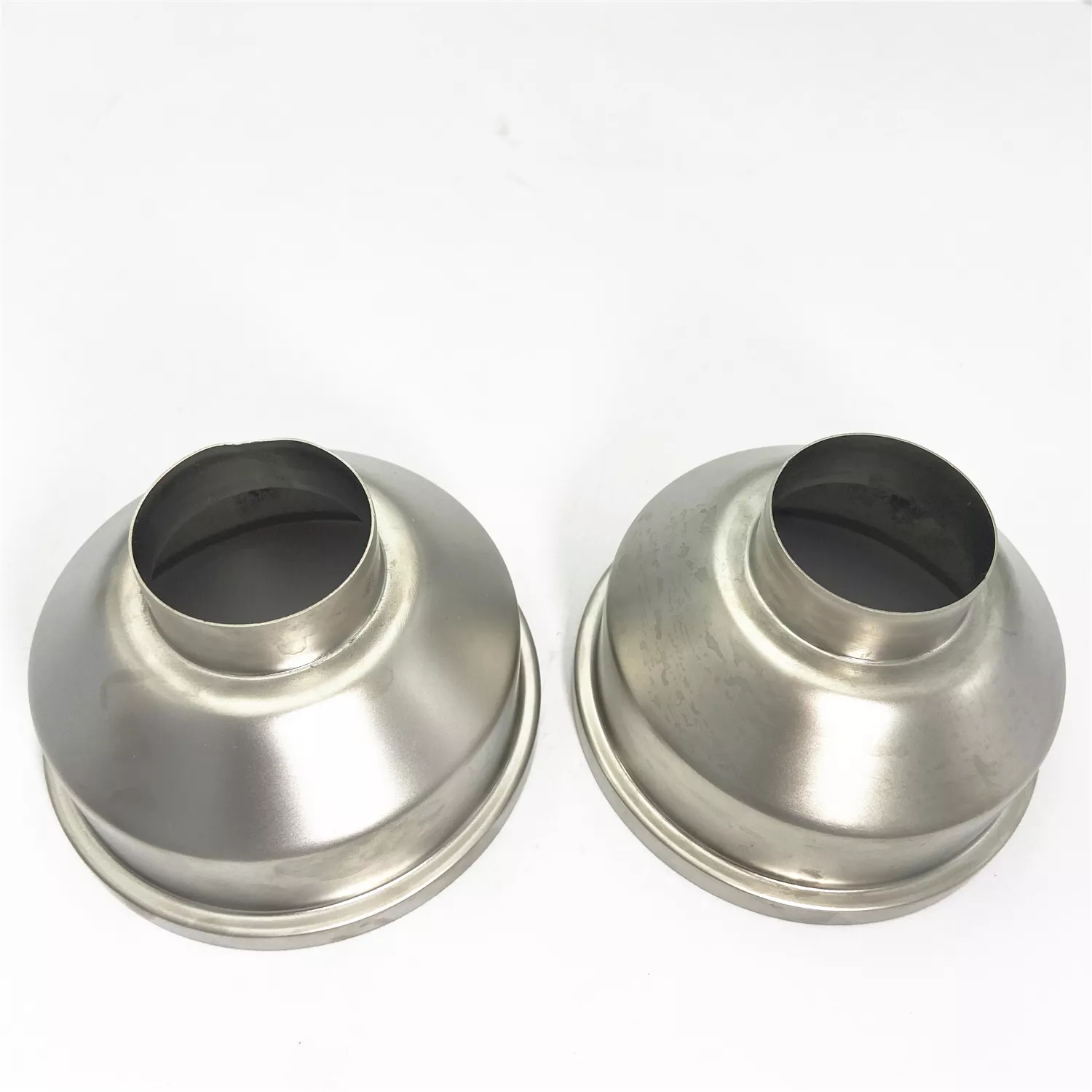
Custom Aluminum Sheet Metal Fabrication and Stamping Parts | Necked Shell Components
-
Model NumberS2402 2407RDrawing Format2D/(PDF/CAD) / 3D(IGES/STEP/STP)
-
MaterialGalvanized Plate / Steel /Aluminum /Stainless Steel Sheet PlateFinishPainting/ Anodizing/ Powder Coating/Nickel Chrome Plating
-
ColorPanton Color and Ral Color SupportedCertificateISO9001/ROHS/IATF16949
-
ProcessSheet Metal Fabricating + CNC + Surface TreatmentLogoAccept Customized Logo
-
PackingPlastic Bag + Carton + Plywood Pallet
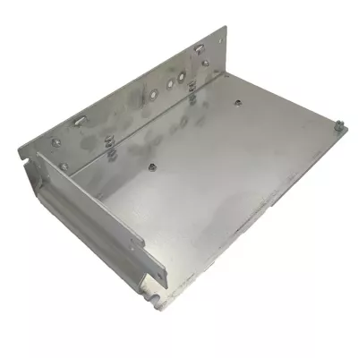
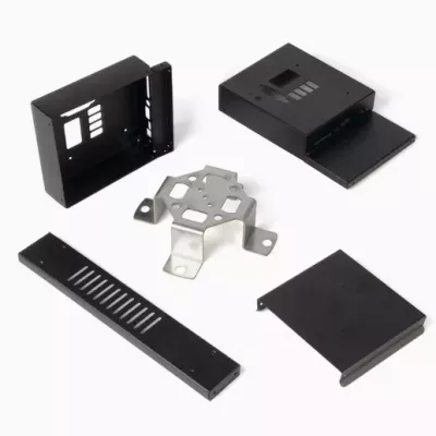
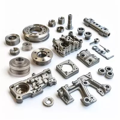
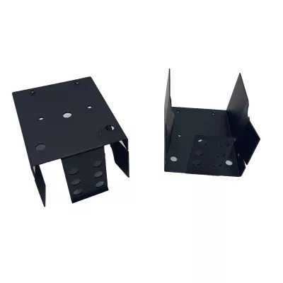
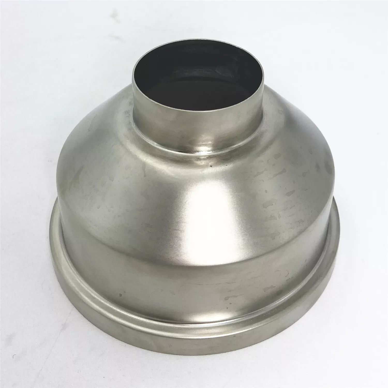
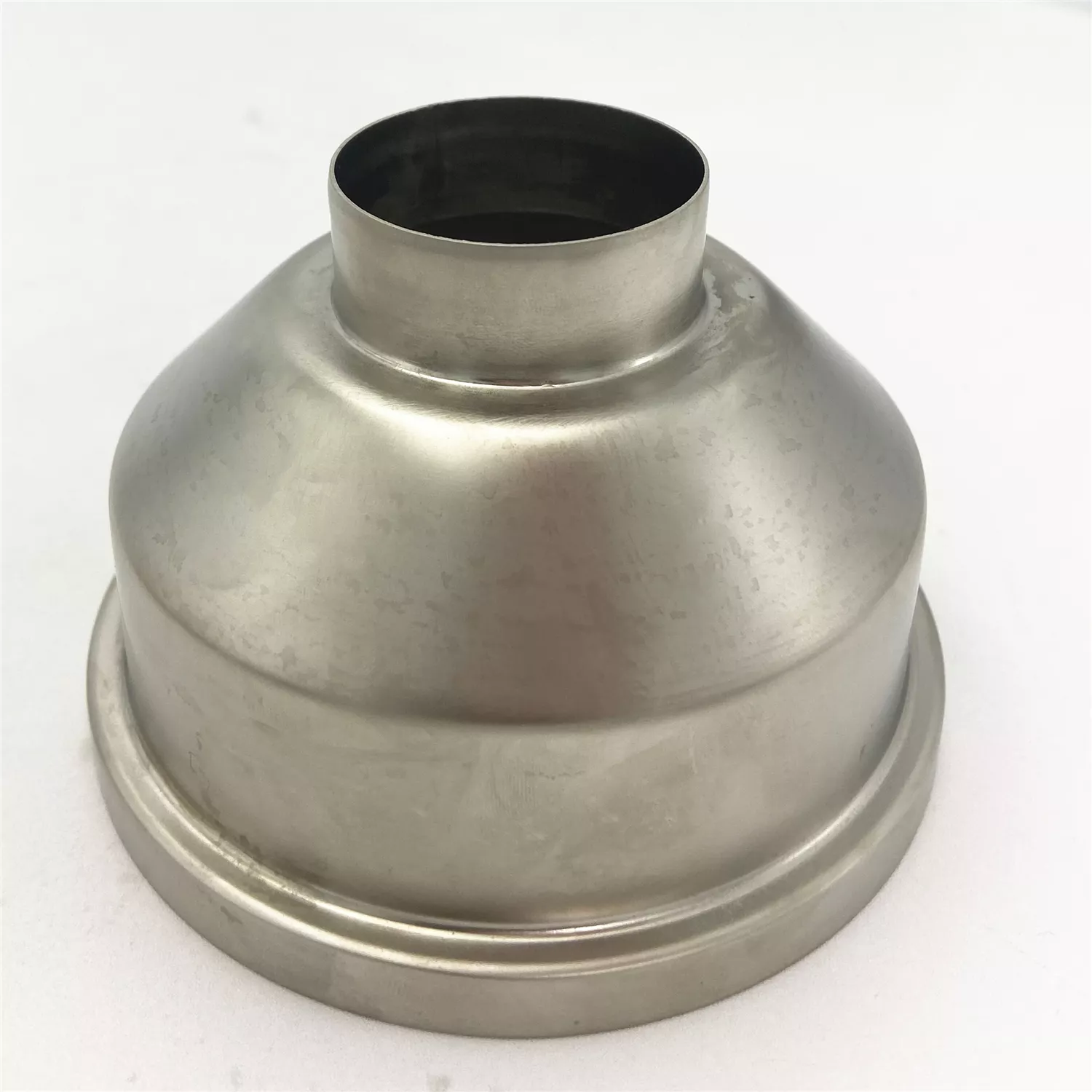
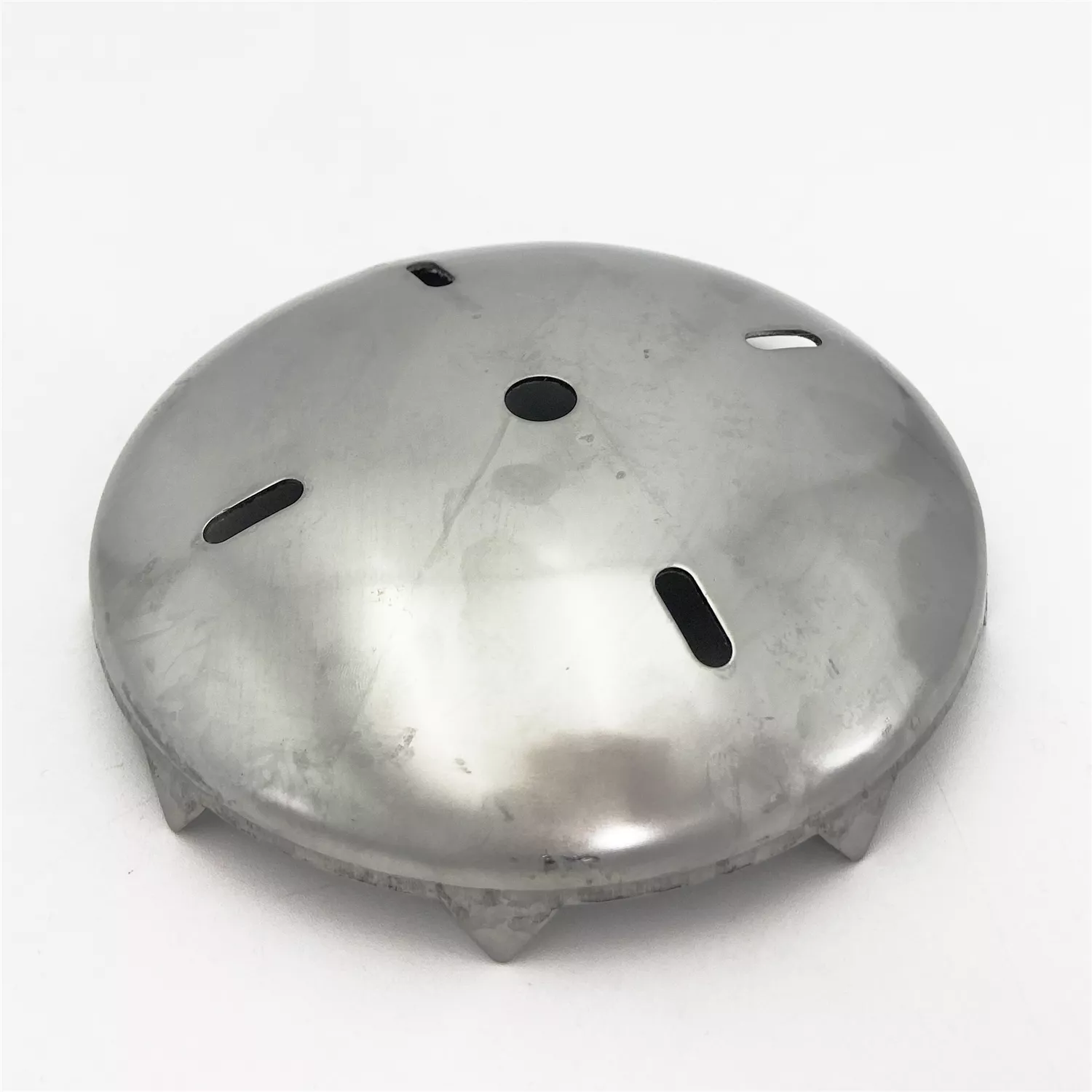
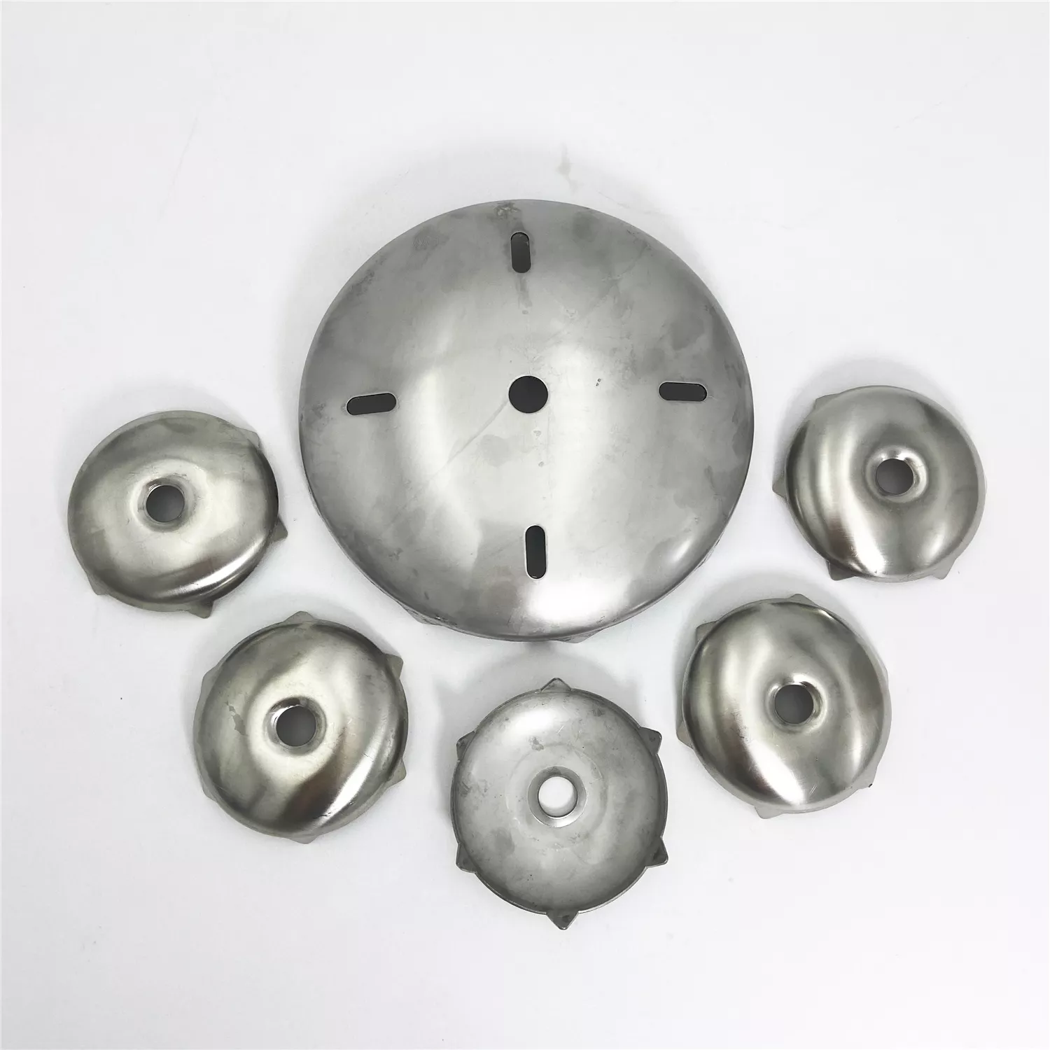
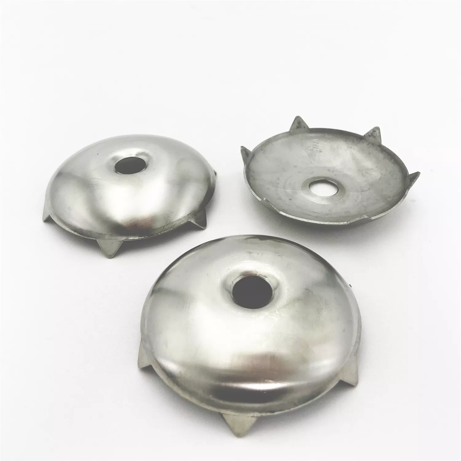
Define each shell through its raised circular neck and stepped lower rim. The two light examples show domed bodies with similar broad geometry. Their appearance does not establish actual aluminum grade, a supplied pair, common dimensions or a particular spinning, stamping or other forming route.
Relate the neck to the lower rim interfaces
Provide sections showing wall geometry and the actual mating components at both ends. Locate contact faces and required clearances from assembly datums. Specify whether either opening needs a defined thread, seal or retention detail rather than inferring a connection standard from the circular form.
- Identify each necked shell and drawing revision.
- Select actual alloy, condition and thickness.
- Dimension neck, dome and stepped-rim contacts.
- Define forming and any secondary CNC requirements.
- Agree finish, interface checks and service evidence.
Choose the sheet material and fabrication plan
Aluminum is the title's material direction, with other listed sheet metals selected separately where requested. State actual grade and required records for the order. Define forming, any cutting or secondary machining and a compatible treatment for that material; the photograph does not independently prove the manufacturing plan.
Accept the finished shell for its intended duty
Mark tolerances with units and final measurement conditions at the neck and rim. Choose color or appearance requirements where needed, including masking at contact surfaces. Any pressure, flow, thermal or environmental requirement needs actual operating conditions and applicable tests.
Supply each shell's PDF/CAD or IGES/STEP/STP drawings, quantities and requested inspection records. Identify differing metals, neck connections and rim interfaces individually so the fabrication proposal follows the correct component definition.