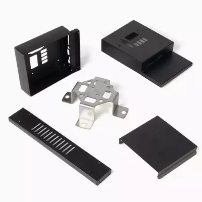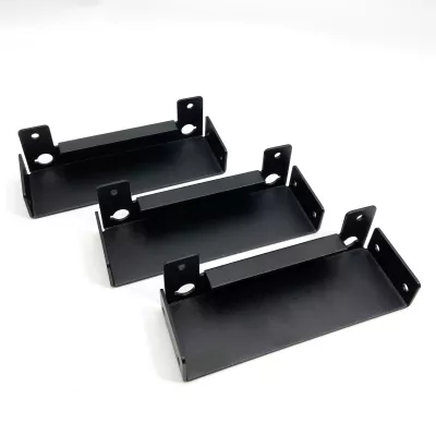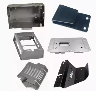
Custom Steel Aluminum Sheet Metal Stamping and Bending Parts | Flanged Tray Components
-
Model NumberS2208 2407RMaterialsteel, stainless steel, aluminum
-
Sizeas drawings or as samplesApplicationMachinery/Industry/car
-
Finishingpowder coating/painting/brushing/polishingProcessbending/punching/laser cutting/stamping
-
ServiceOEM ODMUsagePrecision Metal Stamping Product
-
Packingcarton box+ wood palletTypeOEM Parts
-
EquipmentCNC Bending/Stamping Machine
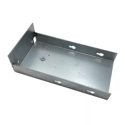
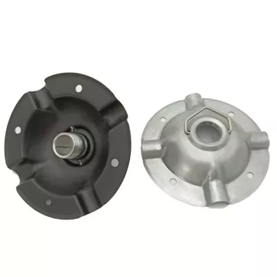
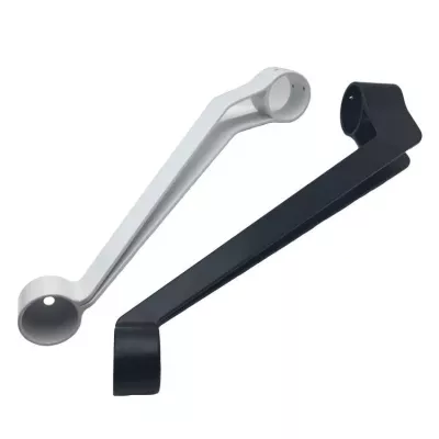
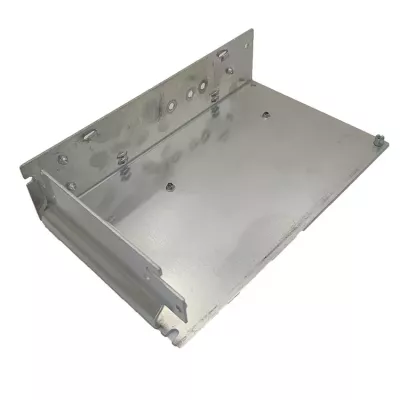
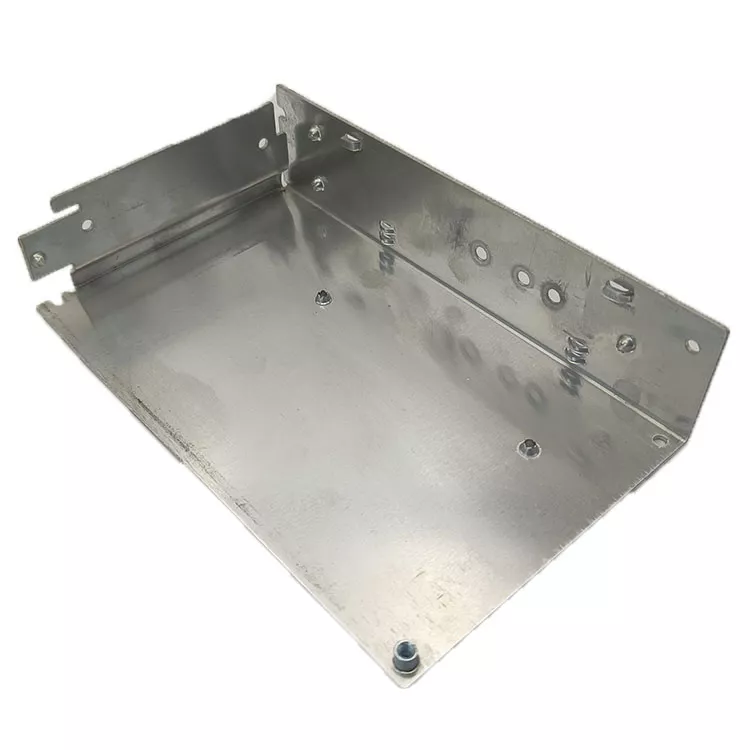
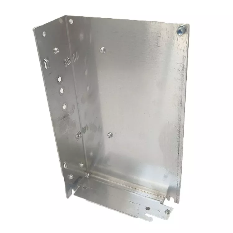
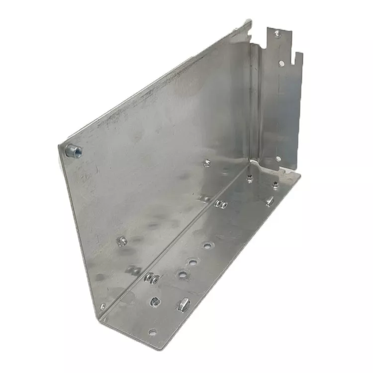
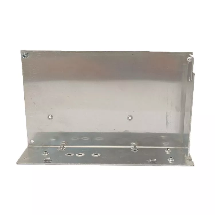
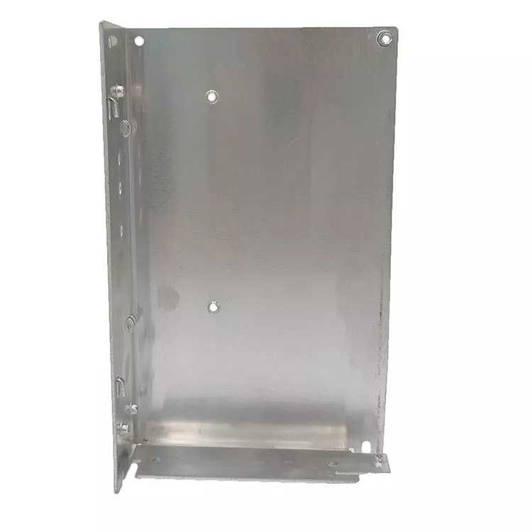
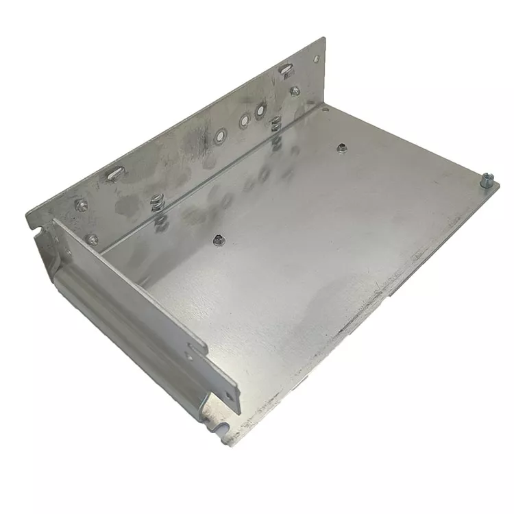
Define the tray component through its broad base, raised flanges and fixing details. The light example shows multiple holes and slots around the formed regions. Those features provide a geometry reference, while actual alloy, thickness and the required cutting or forming route must follow the component specification.
Locate the flanges from the base interfaces
Provide flat and formed drawings, or an agreed sample definition supported by controlled dimensions. Reference holes, slots and contact surfaces to the datums used by adjoining parts. Specify inserts or fasteners separately and identify any pieces included in the delivery rather than assuming a complete assembly.
- Identify the flanged tray and drawing revision.
- Select actual metal grade and sheet thickness.
- Dimension base contacts, openings and formed flanges.
- Define cutting, punching, stamping and bends.
- Agree finish, final inspection and application evidence.
Choose the metal and compatible finish
Steel, stainless steel and aluminum are separate material options. State actual grade and condition with the required documentation. Select powder coating, paint, brushing or polishing individually, including masking and appearance requirements where needed. A light surface does not independently identify alloy or treatment chemistry.
Accept the formed tray against the assembly drawing
Mark tolerances with units and final measurement conditions at the fixing and contact regions. Any load, machinery or automotive requirement needs actual service conditions and applicable tests. Neither the tray shape nor an equipment label establishes a verified capability or qualification.
Include quantities, controlled geometry and requested material or inspection records. Keep the selected fabrication plan and supplied scope explicit when comparing proposals for the intended component.