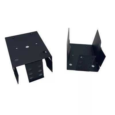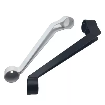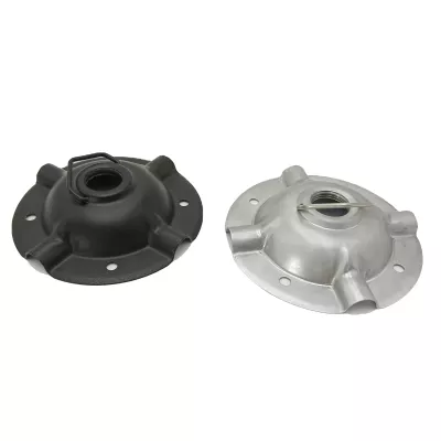
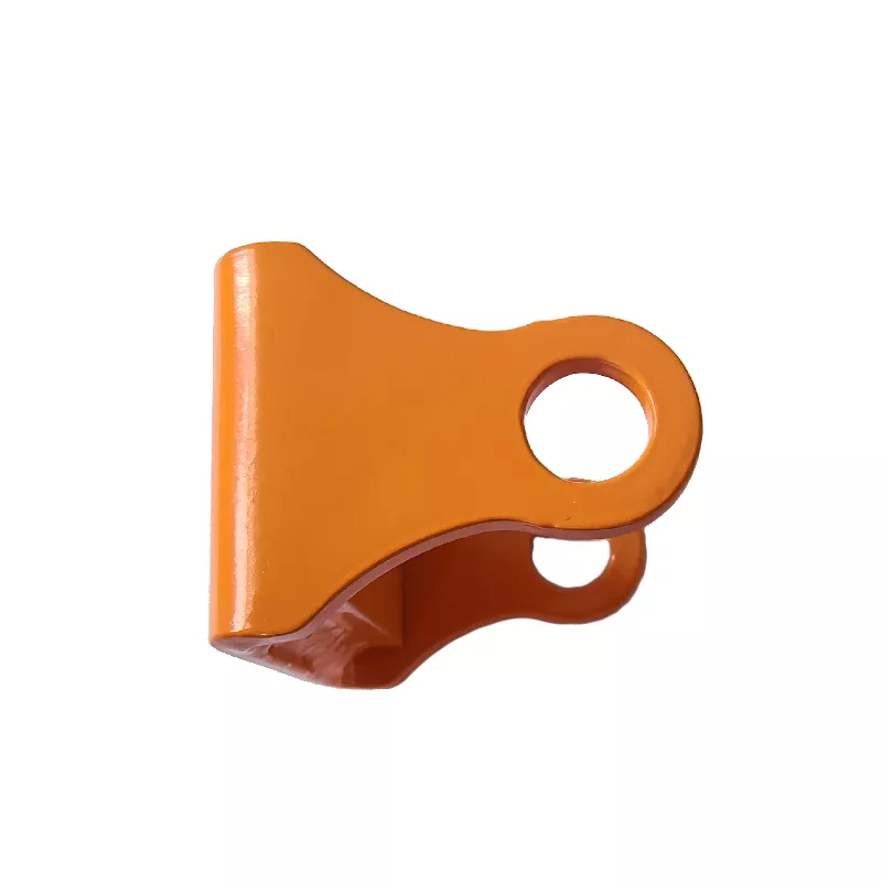
Custom Powder Coated Aluminum Sheet Metal Bending Stamping and Welding Parts | Twin-Ear Brackets
-
Model NumberS2411Material CapabilitiesSteel/Aluminum/copper/Stainless Steel 316/brass
-
ApplicationMachinery/Industry/Home/AutomotiveEquipmentCNC Bending/Stamping Machine/Laser Marking
-
ProcessLaser Cutting Bending StampingKeywordSheet metal fabricating part
-
Surface treatmentPainting\Powder Coating\Plating\PolishingDrawing format2D/3D/CAD/DWG//STEP/PDF/IGS
-
CertificateISO9001/TS16949LogoAccept Customized Logo
-
TechnologyStamping+drilling+assembly
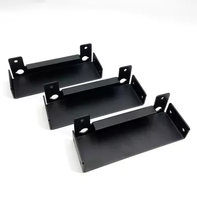
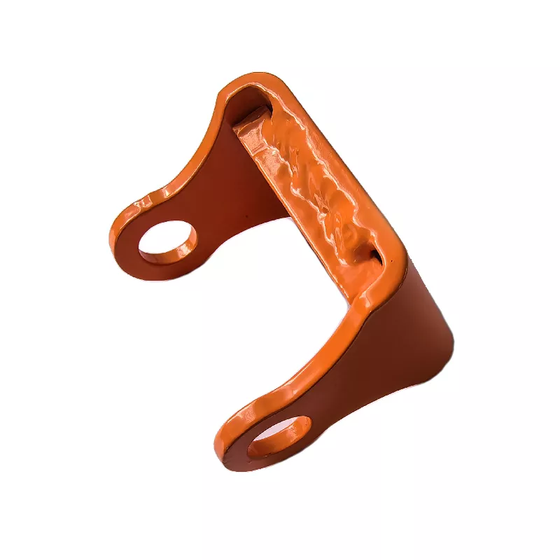
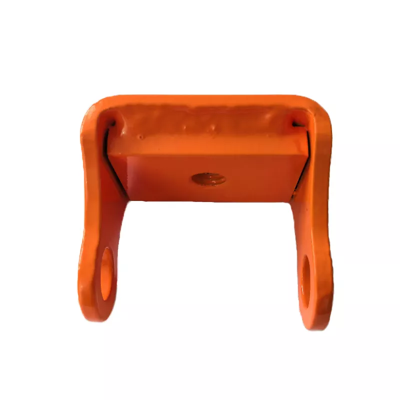
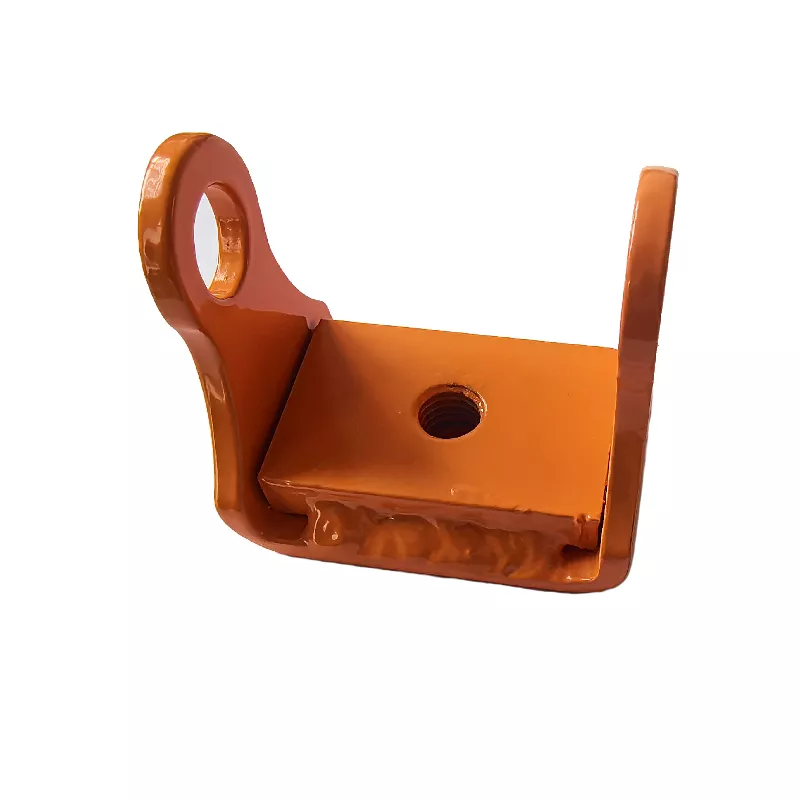
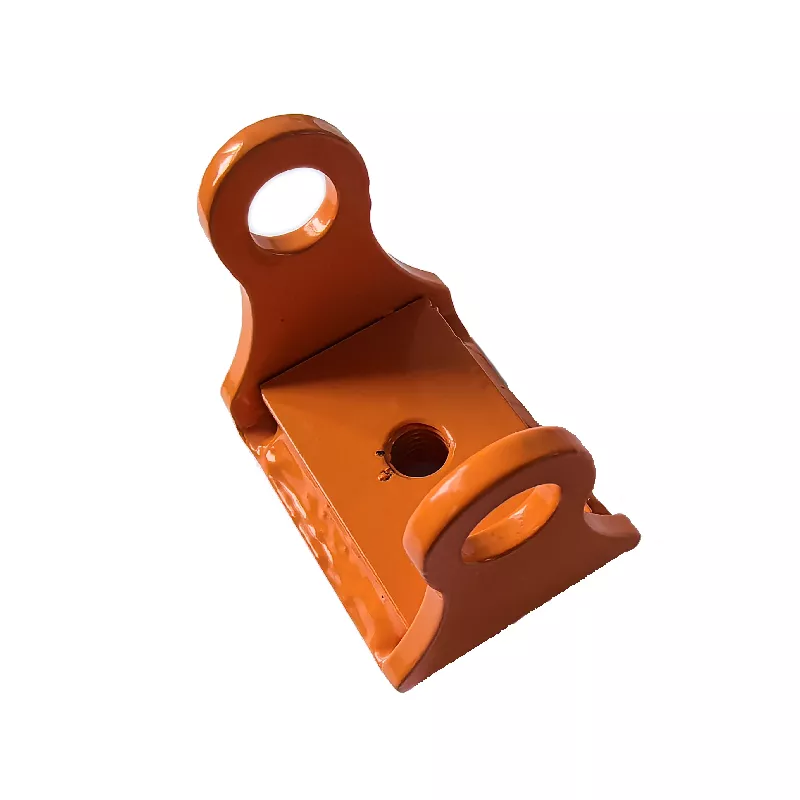
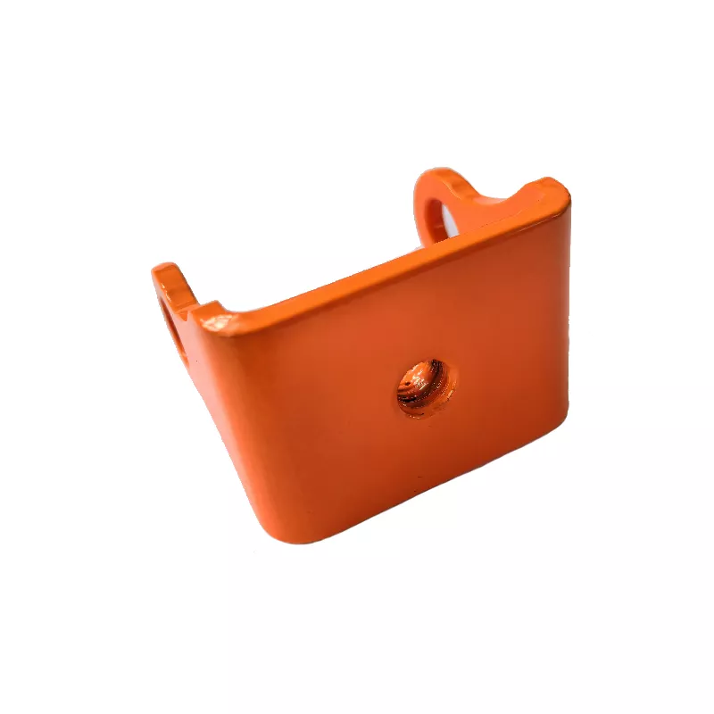
Define the bracket through its two parallel ears, large circular end holes and connecting bridge. The orange example has visible joined or built-up surface regions, but appearance alone does not establish aluminum grade, coating chemistry, a welding method, joint strength or an allowable working load.
Locate the ear holes from the connecting bridge
Provide individual component and assembly drawings with sections through the ears and bridge. Reference hole centers, spacing and contact faces to functional datums. Identify any pin, bolt, insert or adjoining component separately, stating which hardware and assembly operations form part of the proposed delivery.
- Reference the twin-ear bracket and assembly revision.
- Select actual metal and section dimensions.
- Dimension ear spacing, holes and bridge contacts.
- Define forming, joining and compatible coating.
- Agree joint inspection and intended-duty evidence.
Select material and fabrication by component
Aluminum is the named service direction; steel, copper, stainless steel or brass requires a separate grade and condition choice where requested. Define cutting, stamping, bending, drilling and any welding or assembly for the controlled design. Specify join locations and acceptance independently from the bracket outline or a general equipment label.
Accept the bracket after the selected surface treatment
Choose actual powder-coating or another compatible system, with color, masking and appearance requirements. Mark tolerances with units and final measurement conditions at fixing contacts. Any load, joint-strength, environmental or automotive requirement needs actual operating conditions and applicable tests for the defined component.
Include CAD, DWG, STEP, PDF or IGS geometry, quantities and material or inspection documentation. Keep bracket-only supply distinct from a completed pin mechanism and any separately specified installation qualification.