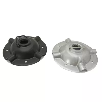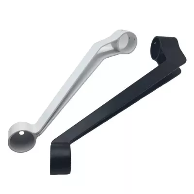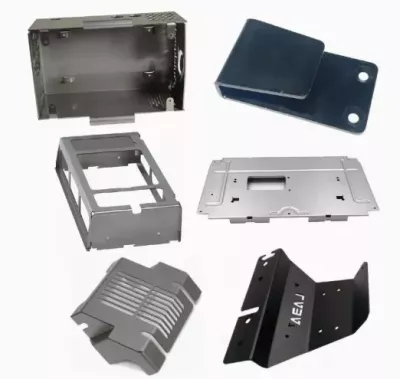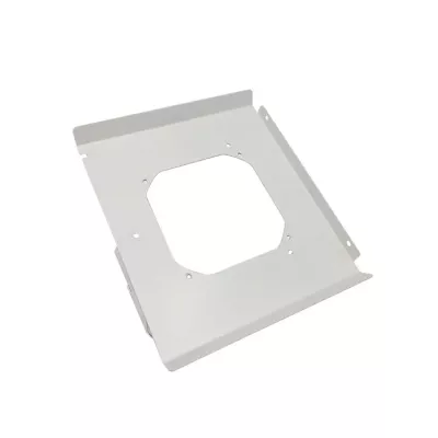
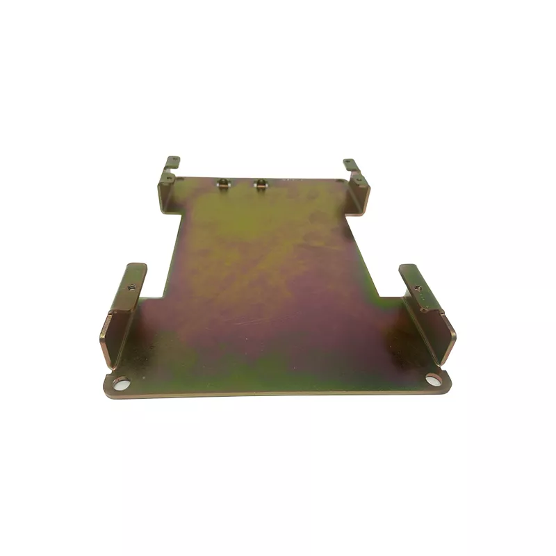
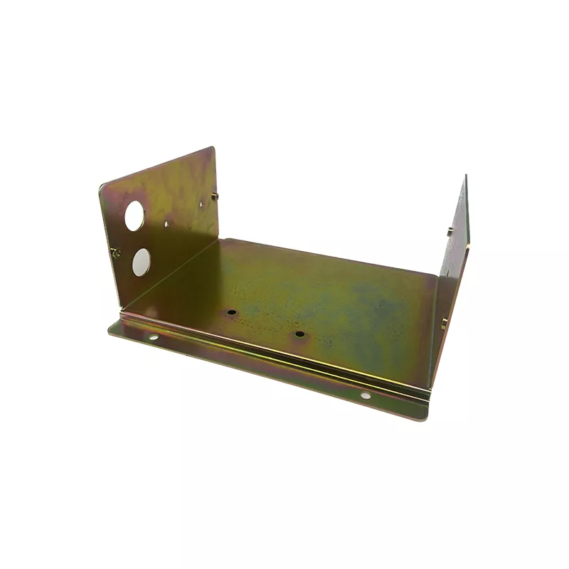
Custom Steel Aluminum Laser Cutting Sheet Metal Bending and Stamping Parts | Open Tray Components
-
Model NumberDML240901Product nameSheet Metal Fabrication
-
Drawing format.step / .stp / .pdfSurface finishingPowder Coating
-
ColorBlack, White and CustomizedApplicationElectronics
-
MOQ100PackagingIndividual Packing
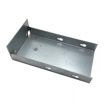
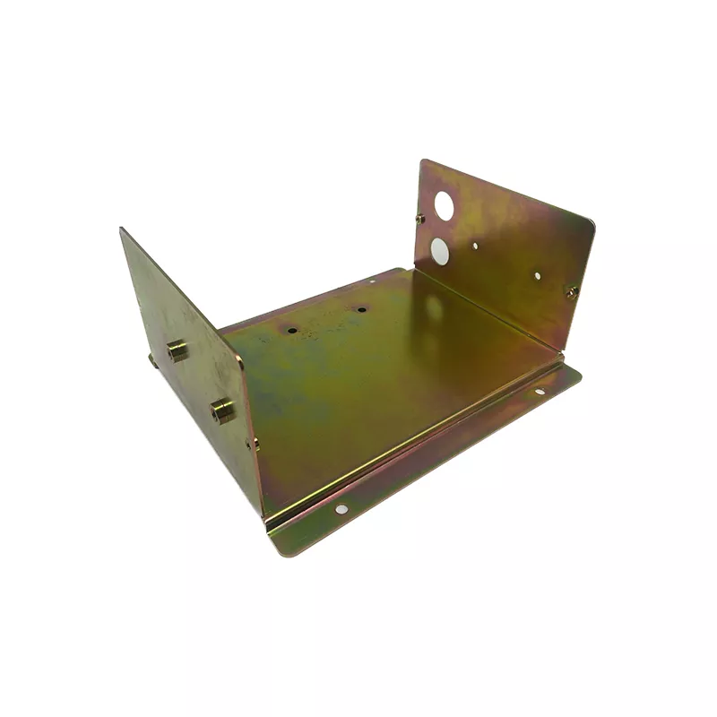
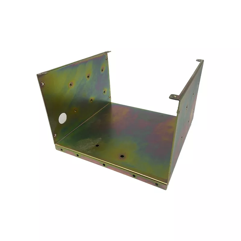
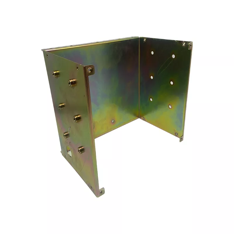
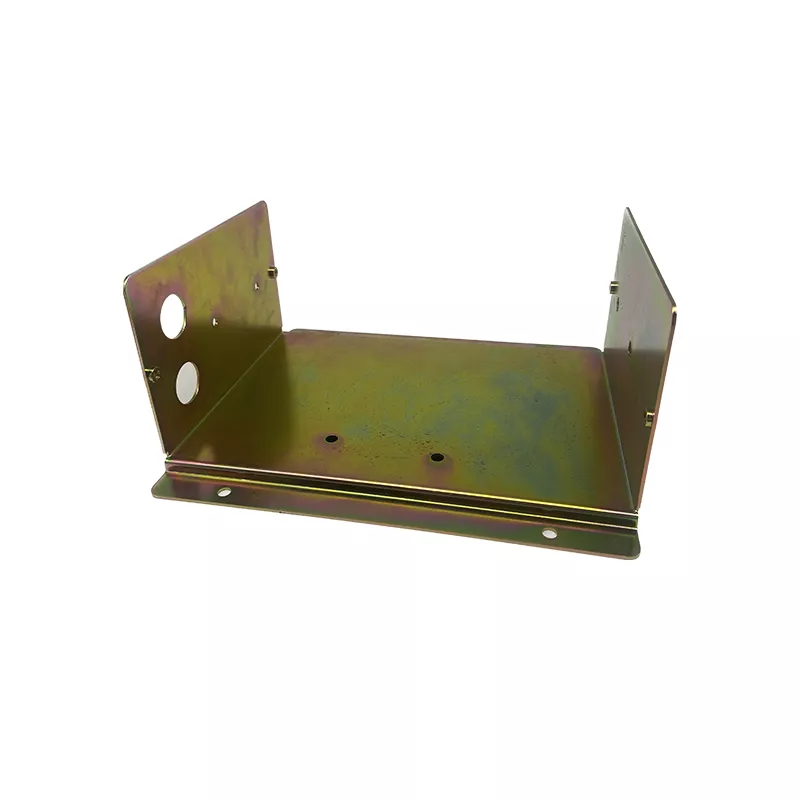
Define the open tray through its opposed end walls, round openings and long front flange. The yellow-green example has two circular holes in one raised wall and smaller fixing details around the formed regions. It does not establish actual steel versus aluminum, coating chemistry or a completed electronics assembly.
Locate the end-wall openings from the tray base
Provide flat and formed drawings with actual mating geometry. Reference circular holes, fixing points and flange contacts to the datums used by adjoining parts. Identify any cover, inserts or hardware included rather than assuming the open tray defines a complete supplied enclosure or a standard mounting kit.
Choose the sheet and required fabrication operations
Steel and aluminum are separate material options. State actual grade, condition and thickness with relevant records, then define laser cutting, stamping, bending and secondary edge work for the controlled design. Surface color and a general process title do not verify the precise manufacturing history of the pictured example.
Accept the tray at its final working contacts
Select a compatible powder-coating or other specified surface system, color reference and masking requirements. Mark tolerances with units and final measurement conditions around the end holes and flanges. Electrical, sealing, load or environmental requirements need actual operating conditions and suitable evidence, separately from an electronics application label.
- Identify the tray and mating-panel drawing revisions.
- Select actual steel or aluminum and thickness.
- Dimension end walls, round openings and front flange.
- Define cutting, forming and the surface specification.
- Agree interface measurements and project tests.
Provide STEP, STP or PDF geometry, quantities and requested material or inspection documentation. A historical ISO or factory phrase does not establish current applicable certification or manufacturing ownership for the delivered component.