Mining Conveyor Chain Connectors | Custom Steel Link and Bow Shackle Enquiries
-
Model NumberS240311MaterialIron /Steel /20CrMnTi
-
ApplicationMine/Auto/IndustryDimensionsCustomer Required
-
Surface treatmentPaint/Powder Coating/Oxidation etcMold makingBy Ourselves
-
ServiceOEM ODMQuality ControlProfessional Inspection
-
PackingIndividually Packed or as per your requirementsProcessForging+Machining(if Need)+Surface Treatment
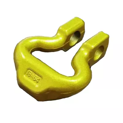
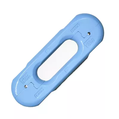
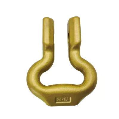
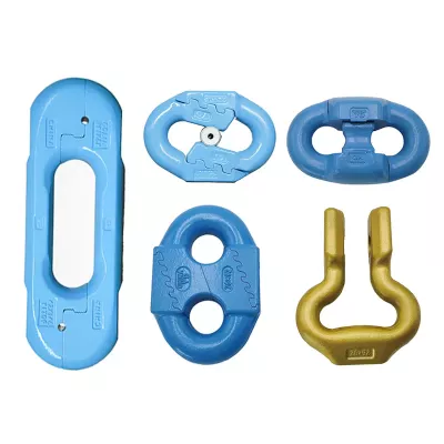
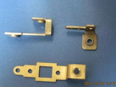
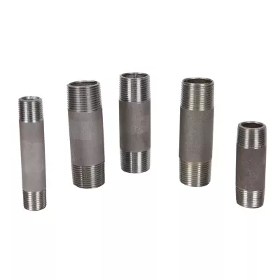
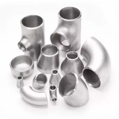
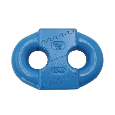
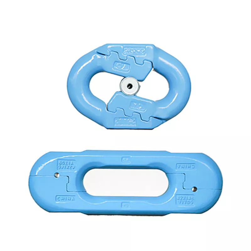
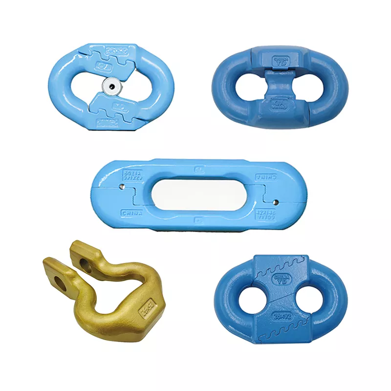
Mining conveyor chain connectors must be selected for the chain and closure arrangement of the intended equipment. This listing includes split links, an elongated connector and an open bow or fork-like component. These examples help identify a component family; they do not define a single interchangeable connector or a complete conveyor assembly.
Identify the connection geometry
For a steel chain link or bow shackle enquiry, identify the exact pictured form and provide its dimensioned drawing. Define the chain-link section, contact geometry, internal opening and available assembly clearance. An open fork with end holes requires a different closure description from a split link with interlocking joints.
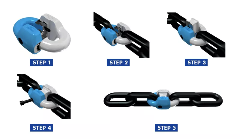
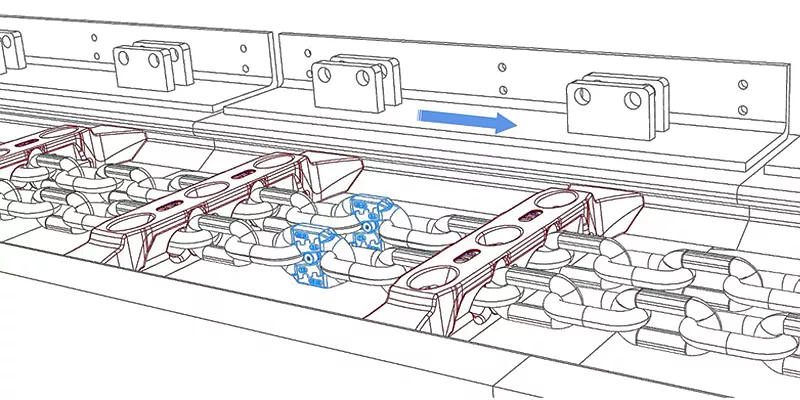
Use S240311 as the catalogue reference together with the drawing revision. Include the required retaining or joining components and state whether the request covers an individual connector body or a finished assembly. The gallery illustration can explain a connection concept, but it is not a substitute for equipment-specific assembly instructions.
Specify the connector material and finished joint faces
The parameter table lists iron, steel and 20CrMnTi as material references. Choose the material and condition for the requested design, along with any required documentation. Neither the blue or yellow appearance nor a raised mark establishes the actual alloy, coating or heat treatment of the order.
The listed process is forging with machining if needed and surface treatment. Mark the closure faces, bores and other fitted features that need machining or dimensional inspection. Define the finished dimensions and selected surface treatment together so that the acceptance requirements apply to the component as supplied.
Confirm the conveyor-duty requirements
- Identify the connector design, chain specification and drawing revision.
- Define closure parts, clearances and finished interface dimensions.
- Select material, condition, treatment and supporting records.
- State operating duty, quantity and inspection requirements.
- Mark joint faces and bores that require machining after forging.
Where the application depends on load capacity, fatigue performance or equipment approval, agree the applicable evidence before purchase. The generic mining application and multiple product photographs do not establish those properties. A useful enquiry connects one defined connector geometry to the actual conveyor chain and its acceptance criteria.