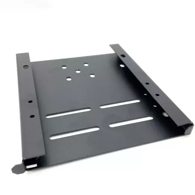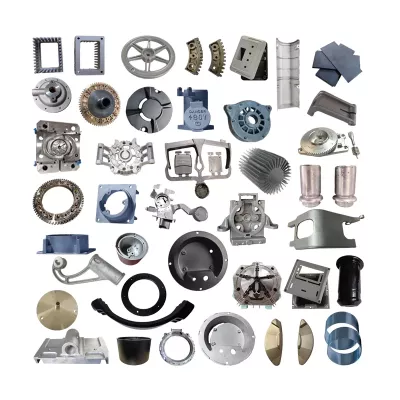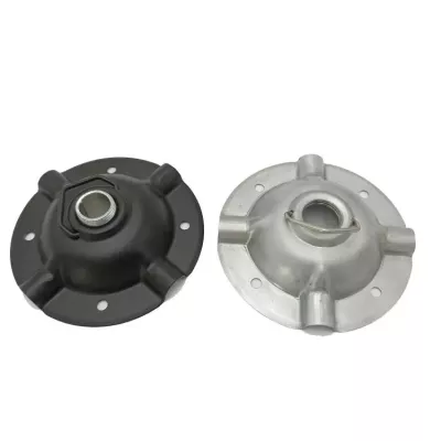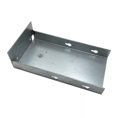
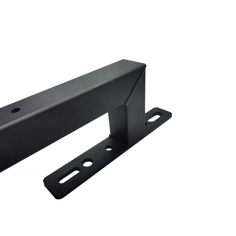
Custom Aluminum Steel Sheet Metal Stamping and Bending Parts | Cylindrical Fork Brackets
-
Model NumberDmetalProduct nameSheet Metal Fabrication
-
Drawing format.step / .stp / .pdfSurface finishingPowder Coating
-
ColorBlack, White and CustomizedApplicationElectronics
-
MOQ100PackagingIndividual Packing
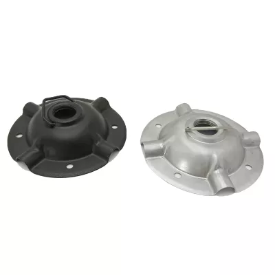
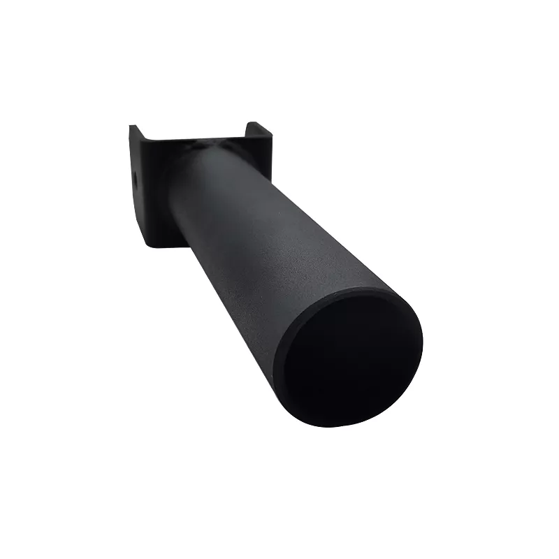
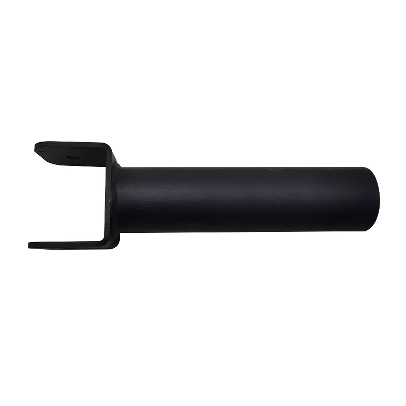
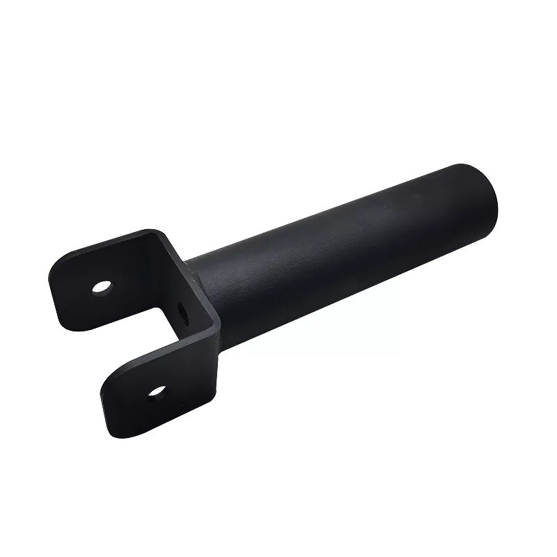
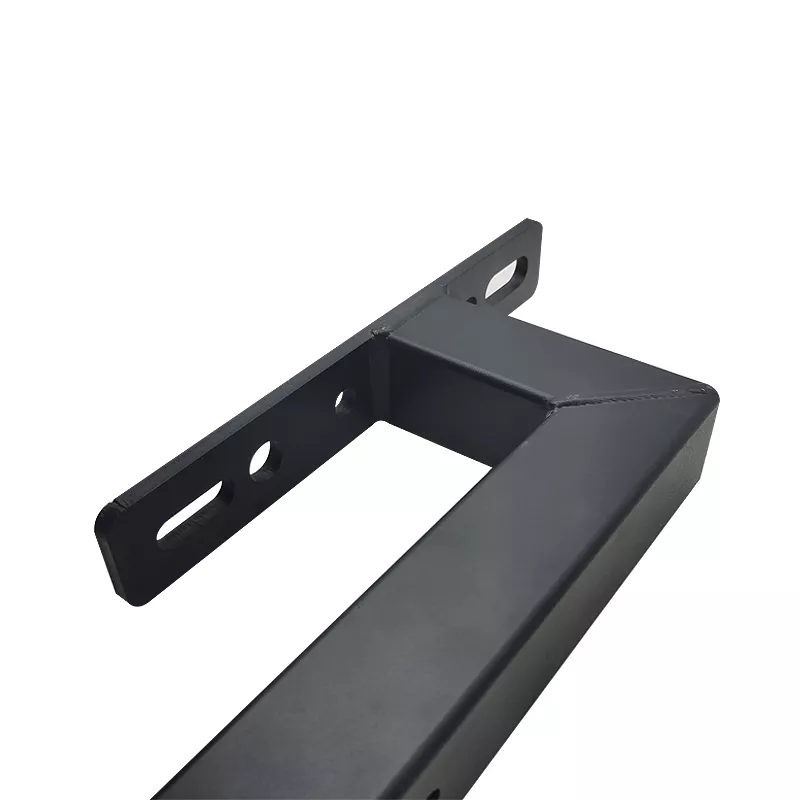
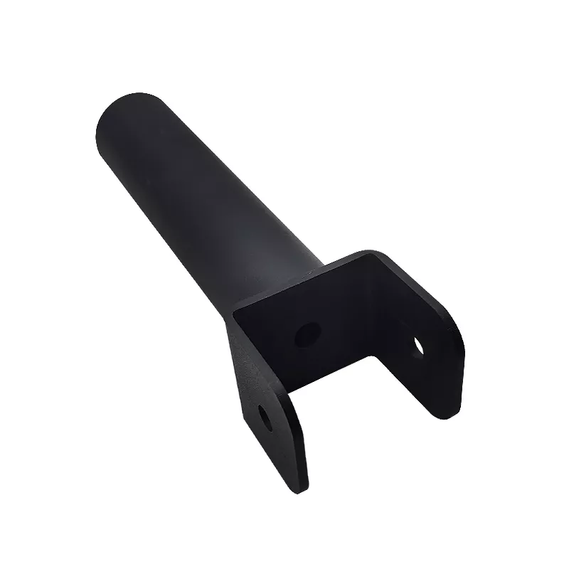
Define the component through its long cylindrical region and open fork-like bracket. The dark example has two side plates with fixing holes near the fork end. Its appearance does not establish actual aluminum or steel grade, the joining method or a verified load-bearing and mounting function.
Relate the cylindrical region to the fork
Provide sections, actual connection geometry and mating-part drawings from assembly datums. Locate side-plate holes and contact faces, including required clearances or retention details. Identify which pieces are joined and which hardware is included rather than inferring a welding method or complete assembly from the photograph.
Select metal and the required forming operations
Aluminum and steel are separate material choices. Specify actual grade, condition and section requirements for each supplied piece. Define cutting or stamping, bending and any joining or secondary machining where required by the design. A general service title is not independent evidence that every operation has been performed on the example.
- Reference the cylindrical fork component and revision.
- Specify actual metal and section requirements.
- Dimension fork holes, contacts and cylindrical interface.
- Define forming, joining and powder-coating scope.
- Agree final inspection and intended-use evidence.
Accept the finished interfaces for their actual duty
Specify the fork-hole and cylindrical-interface acceptance from common assembly references, stating units and the final supplied condition. Specify compatible coating, color and masking where needed. Any load, joint-strength, environmental or functional requirement needs actual operating conditions and applicable tests; appearance alone establishes neither capacity nor machine compatibility.
Include STEP, STP or PDF drawings, quantities and required material or inspection records. Keep supplied hardware and joined-component scope explicit when comparing fabrication proposals.