Custom Steel Stainless Steel Sheet Metal Stamping and Bending Parts | Domed Flange Components
-
Model Number2035Materialsteel, stainless steel
-
SizeCustomized sizeApplicationMachinery/Industry/car
-
ColorCustomized ColorProcessStamping
-
ServiceCustomized OEMUsagePrecision Metal Stamping Product
-
PackingCartonTypeOEM Parts
-
EquipmentCNC Bending/Stamping Machine
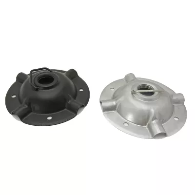
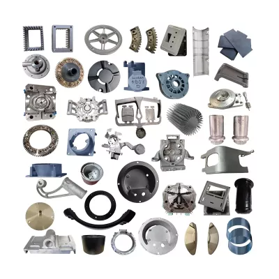
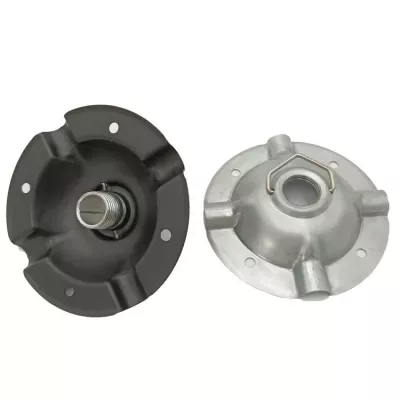
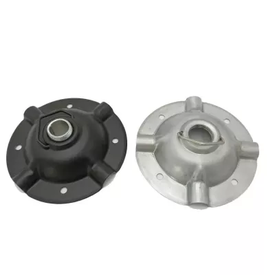
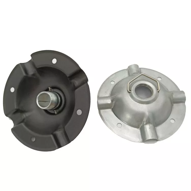
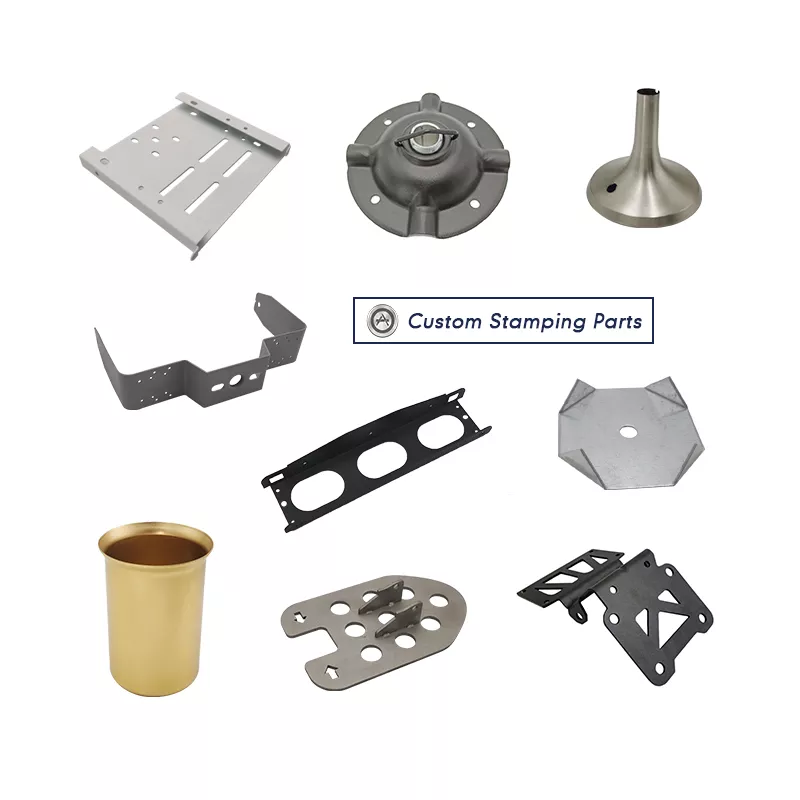
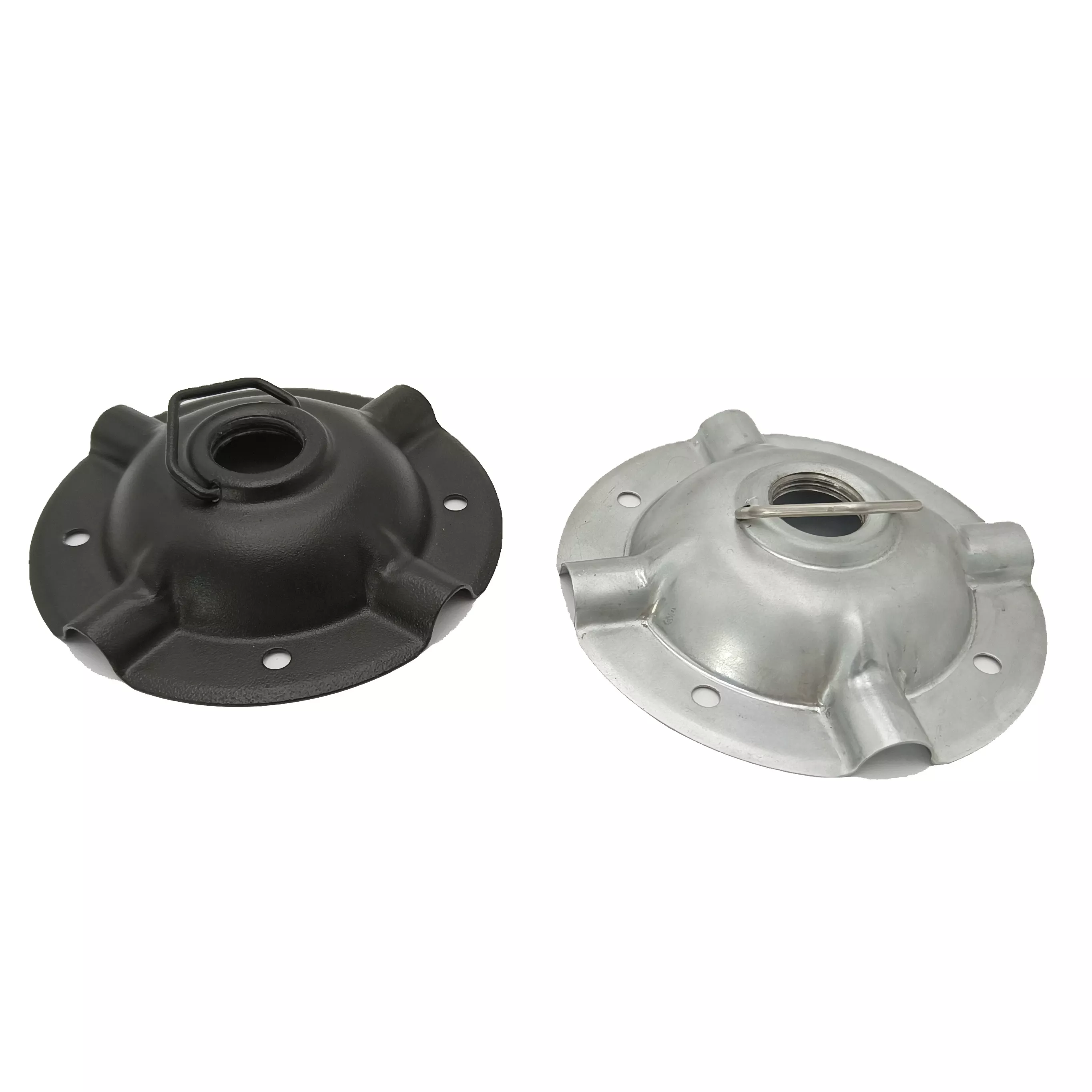
Define the domed flange component through its central neck, radial raised regions and fixing holes. The dark and light examples share a broad form also used elsewhere in the catalogue. Their appearance does not establish a separate engineering specification, actual steel grade or a particular stamping or CNC-bending operation.
Locate the neck and flange working contacts
Provide sections, connection requirements and mating-component drawings from assembly datums. Dimension fixing holes and any contact or clearance surfaces that control installation. Specify whether the opening is plain, threaded or another defined interface rather than deriving the connection standard from the photograph.
Define the actual sheet-forming plan
Choose steel or stainless steel grade, condition and thickness with required material records. Review cutting, stamping, forming and any secondary work against the controlled geometry. A listed equipment name does not independently verify current machinery capability or prove that every example was made by CNC bending.
Accept the formed part in its delivered condition
Mark tolerances with units and final measurement conditions at the neck, flange and fixing interfaces. Specify compatible treatment and appearance requirements. Any pressure, load, machinery or automotive requirement needs actual operating conditions and applicable evidence for the chosen design.
- Identify the domed component and mating drawing.
- Select actual steel grade, condition and thickness.
- Dimension neck, formed regions and flange holes.
- Define fabrication operations and compatible finish.
- Agree dimensional and application acceptance records.
Provide quantities and controlled neck-and-flange geometry for each required configuration. Keep metal and connection choices separately identified so a shared example image cannot establish a common material, duty or supplied scope.