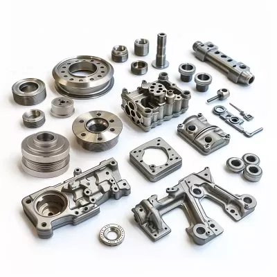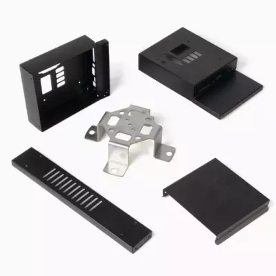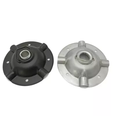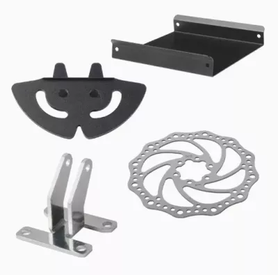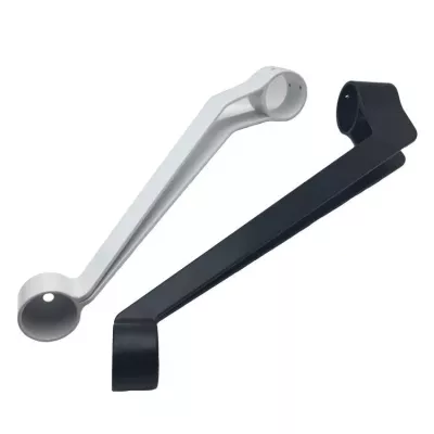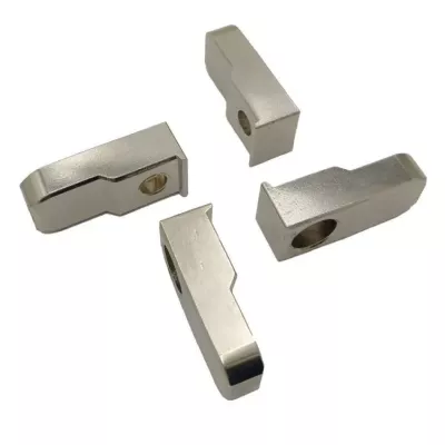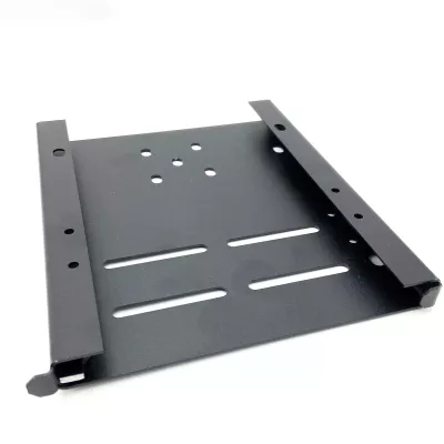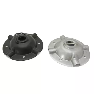
Custom Powder Coated Sheet Metal Stamping Parts | Bent Tray Bracket Components
-
Model NumberRTS-02Materialsteel/metal/aluminum
-
ApplicationElectronicsDimensionsCustomer Required
-
Surface treatmentPaint/Powder coating/oxidation etcMold makingBy ourself
-
ProcessDie Casting-deburring- MachineryServiceOEM ODM
-
FeatureEco FriendlyQuality ControlProfessional Inspection
-
PackingCarton
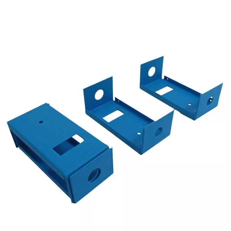
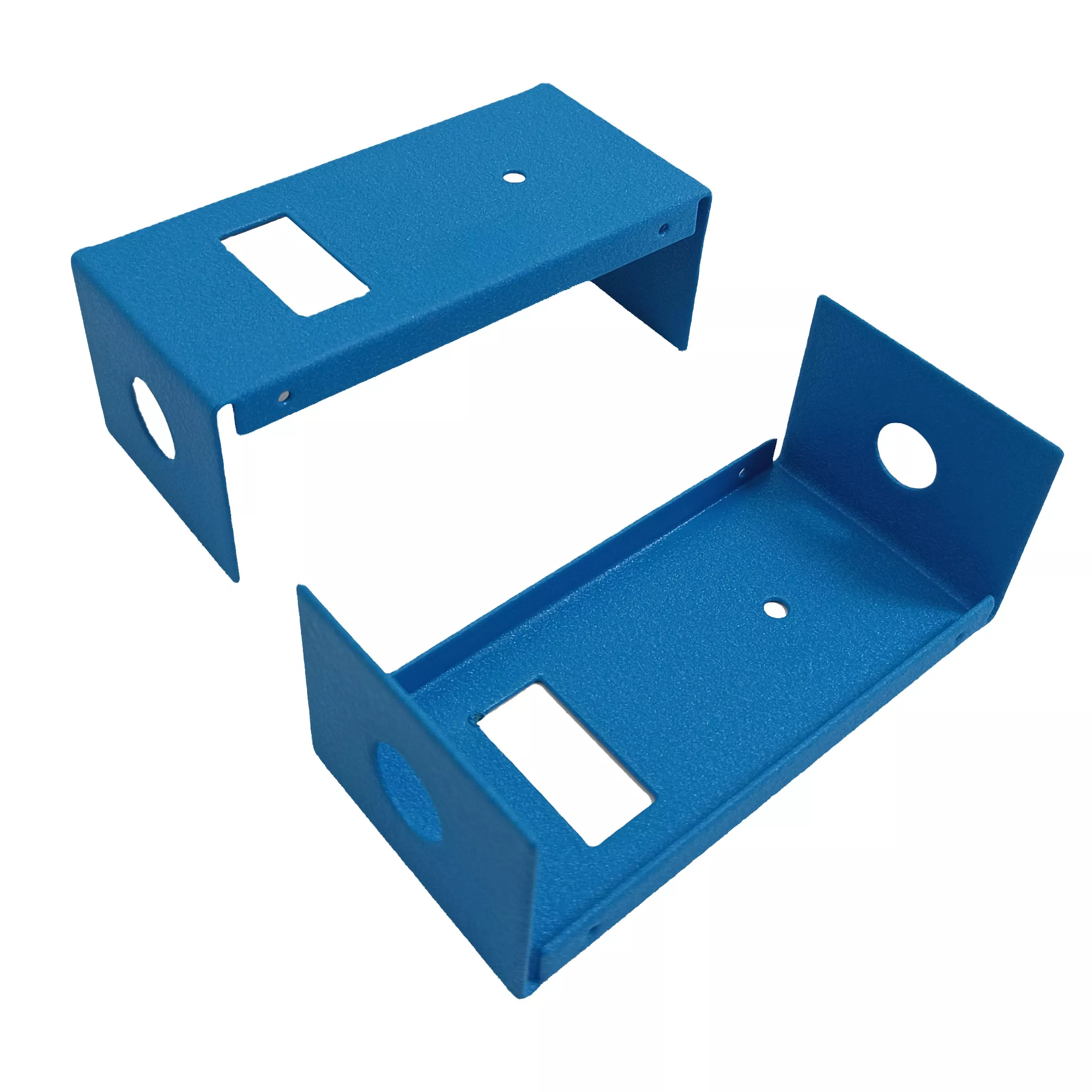
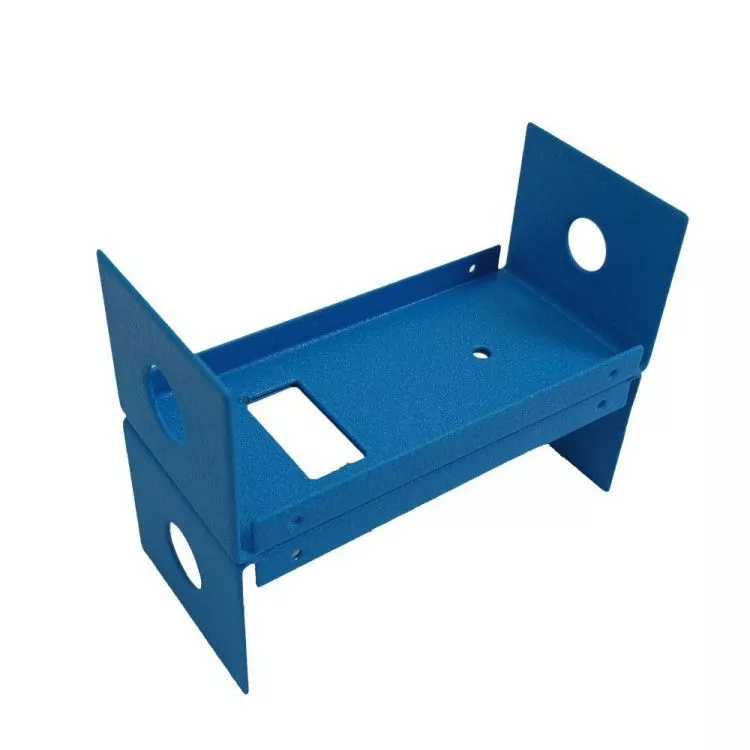
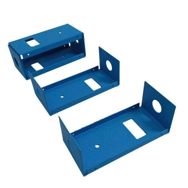
Identify each tray bracket by its base openings and bent end walls. The three blue examples have round side openings and rectangular openings in their base regions. Their color and grouping do not establish coating chemistry, common dimensions, actual metal grade or a supplied set.
Coordinate the base and upright end interfaces
Provide flat and formed drawings, locating side openings, rectangular cutouts and fixing details from assembly datums. Identify adjoining components and any contact or clearance requirements. Assign separate item references and quantities where different bracket configurations are required, with any included hardware clearly listed.
Specify the sheet metal and forming route
Select the actual steel, aluminum or other agreed grade, condition and sheet thickness. Define cutting or stamping, bending and subsequent edge work for that design. A generic process field does not establish that a bent sheet bracket must be die cast, and the photograph does not independently prove its production history.
Define powder coating and final acceptance
State the actual compatible coating system, color reference and appearance criteria where powder coating is requested. Mark masking requirements and final measurement conditions at mating surfaces. Blue appearance alone does not establish coating durability, thickness or chemistry.
- Reference each bent tray bracket and drawing revision.
- Specify actual metal grade and sheet thickness.
- Dimension base cutouts and upright round openings.
- Define fabrication and the selected coating system.
- Agree interface checks and required inspection records.
Include quantities, controlled geometry and material documentation. Any load, electrical or environmental requirement needs actual service conditions and applicable evidence for the component and its intended assembly.