Custom Steel Plate Bending Welding and Laser Cutting Parts | Powder Coated Channel Components
-
Model NumberS2501Material CapabilitiesSteel/Aluminum/copper/Stainless Steel 316/brass
-
ApplicationMachinery/Industry/Home/AutomotiveEquipmentCNC Bending/Stamping Machine/Laser Marking
-
ProcessLaser Cutting Bending StampingKeywordSheet metal fabricating part
-
Surface treatmentPainting\Powder Coating\Plating\PolishingDrawing format2D/3D/CAD/DWG//STEP/PDF/IGS
-
CertificateISO9001/TS16949LogoAccept Customized Logo
-
TechnologyStamping+drilling+assembly
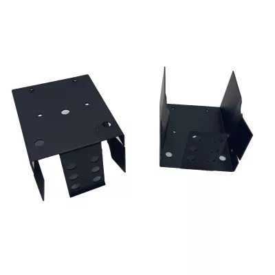
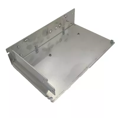
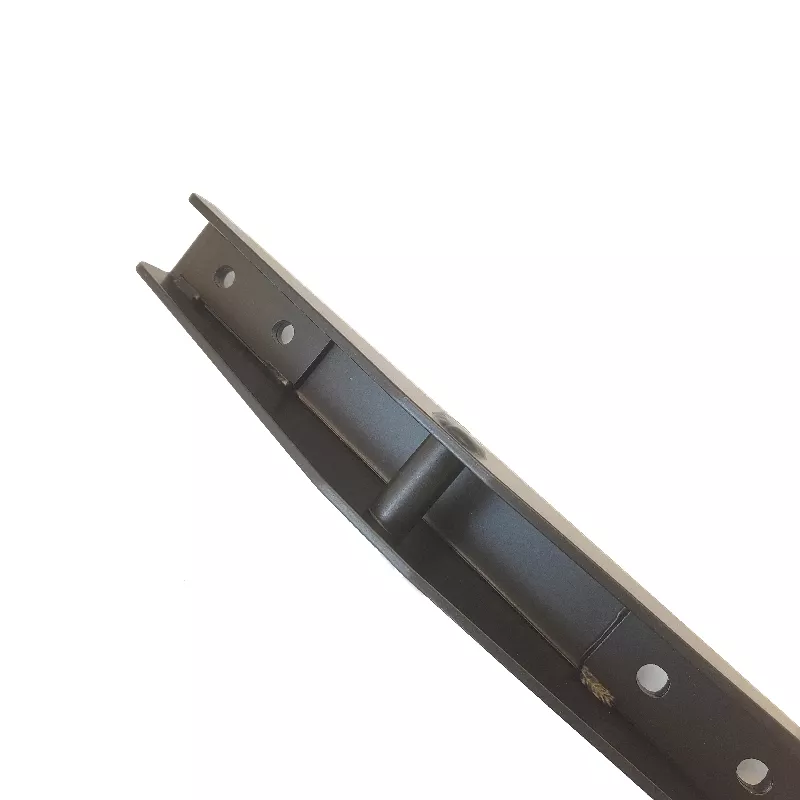
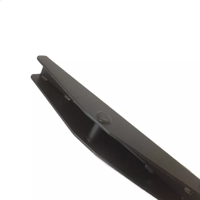
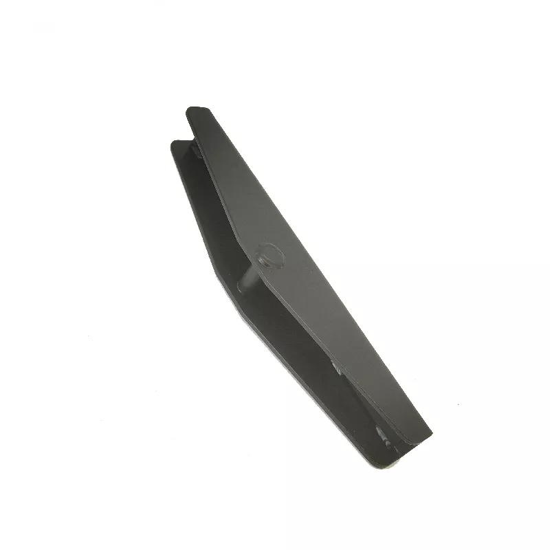
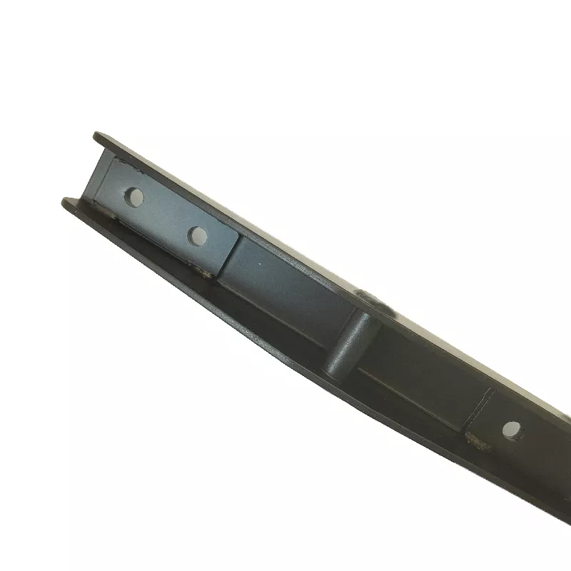
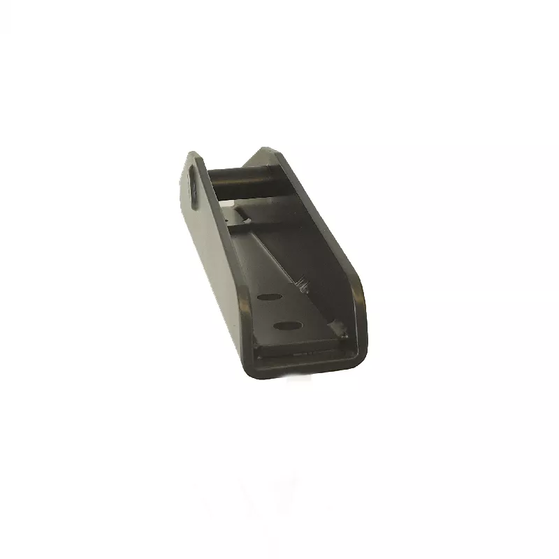
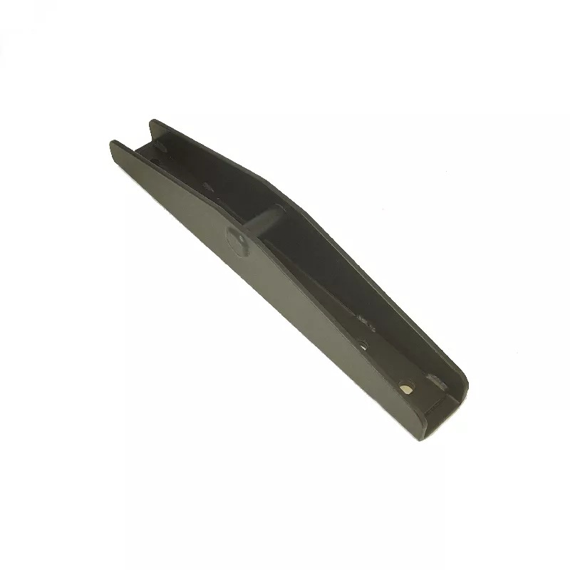
Specify the channel component through its parallel side walls, shaped ends and internal regions. The dark example shows small openings and visible joining or reinforcing details along an elongated body. It does not independently establish steel grade, section dimensions, a welding method, joint strength or allowable working load.
Locate side-wall contacts and internal pieces
Provide individual component sections and the assembly relationship between walls, base and any reinforcing elements. Reference holes and contact surfaces to functional datums, showing actual mating geometry. Identify included hardware and joined pieces separately rather than assuming a channel photograph establishes a complete structural assembly.
- Reference channel, reinforcement and assembly revisions.
- Specify actual steel and section dimensions.
- Locate side walls, openings and working contacts.
- Define cutting, forming, joins and selected finish.
- Agree joint checks and application acceptance records.
Choose fabrication and welding requirements separately
Steel is the title material direction; aluminum, copper, stainless steel or brass requires a separate grade selection where requested. Define laser cutting, bending, stamping, drilling and any welding for each controlled piece. If joining is required, specify locations, construction and inspection criteria independently from a general service or equipment entry.
Inspect the channel in its delivered condition
Select compatible powder coating, paint, plating or polishing where needed, with color, masking and appearance requirements. Define tolerance units and final inspection conditions at the channel's side-wall and fixing contacts. Any load, joint-strength, machinery or automotive requirement needs actual operating conditions and suitable evidence for the intended design.
Provide CAD, DWG, STEP, PDF or IGS geometry, quantities and material documentation. Keep component-only, joined-channel and completed-equipment supply scopes distinct when defining acceptance and comparing fabrication proposals.