OEM Aluminum CNC Milling Turning and Drilling Parts | Forked Component Enquiries
-
CNC Machining or NotCnc MachiningTypeBroaching, DRILLING, Etching / Chemical Machining, Laser Machining, Milling, Other Machining Services, Rapid Prototyping, Turning, Wire EDM
-
Material CapabilitiesAluminum, Brass, Bronze, Copper, Hardened Metals, Precious Metals, Stainless Steel, Steel AlloysMicro Machining or NotMicro Machining
-
Model Number2110MaterialAluminum
-
Product nameCnc Maching PartsMOQ100pcs
-
CertificationISO9001Tolerance0.01mm
-
Delivery Time30 DaysOEM/ODMAccecpted
-
PaymentT/T:30% Deposit
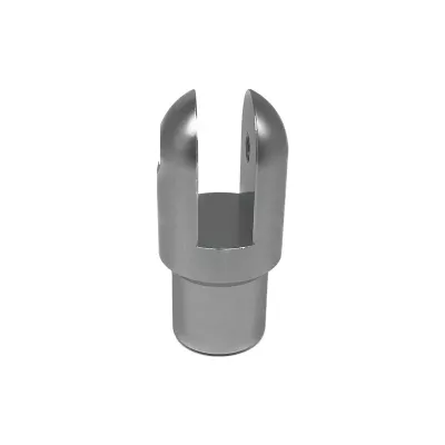
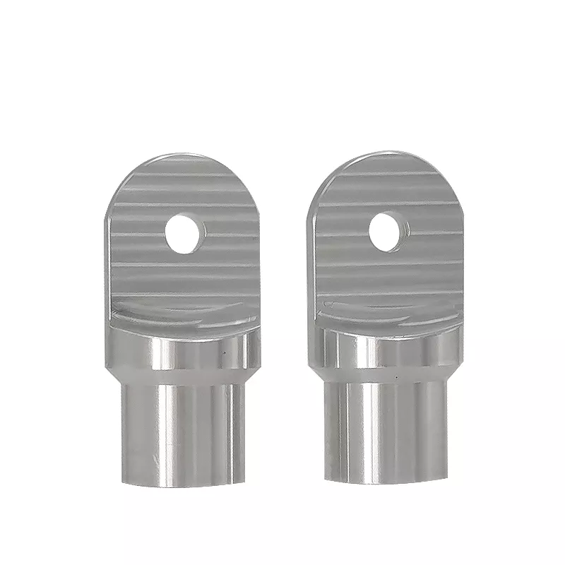
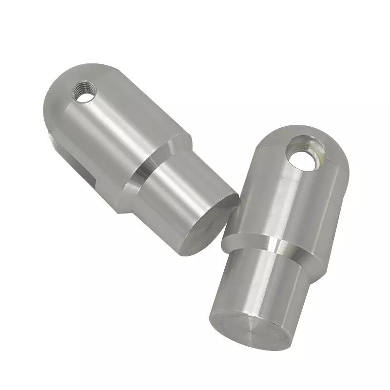
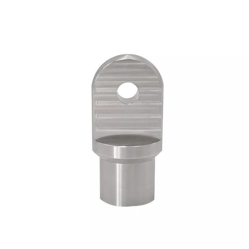
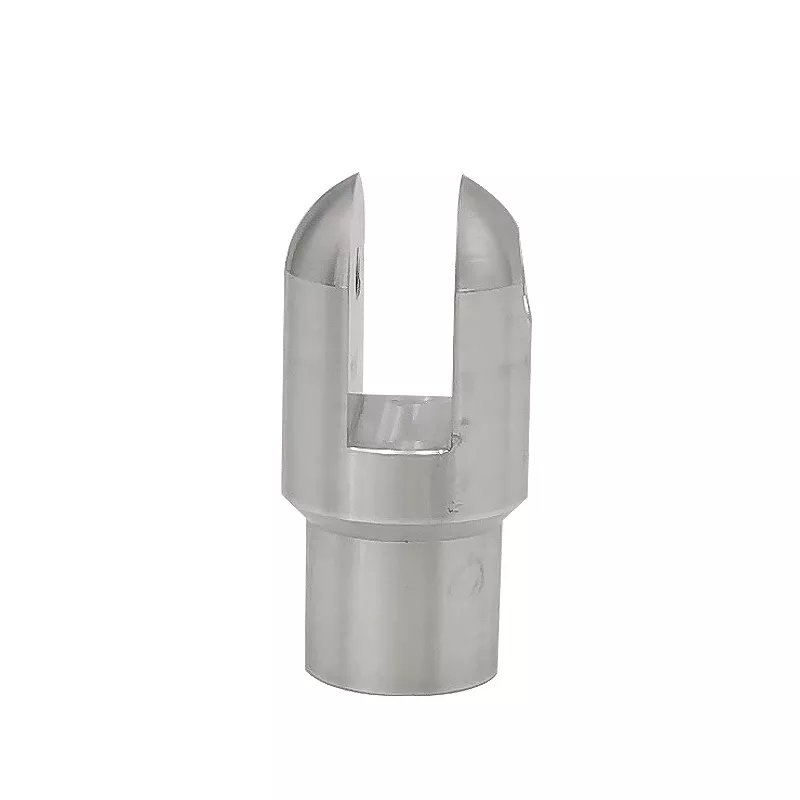
The forked example combines a stepped cylindrical base with two upright arms and a wide channel between them. An OEM aluminum component enquiry should explain how those features join the intended assembly. The photograph is useful for identifying the form, but it supplies neither a complete interface specification nor the working purpose of the part.
Describe the arms, channel and cylindrical base
Show the arm spacing, slot width, wall sections and end profiles on the drawing. Relate those dimensions to the lower cylindrical section and any shoulder used to locate the component. Identify the surfaces that contact mating parts and the clearances required around the arms.
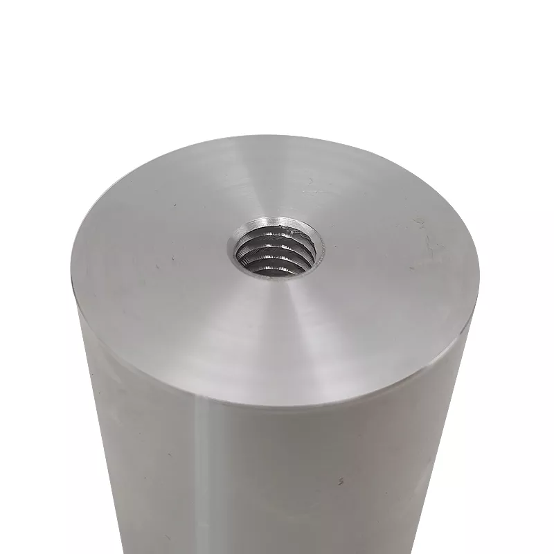
Locate holes from defined reference surfaces and specify any thread or cross-hole relationship. Different operations may be needed for the cylindrical outline, the channel and the holes. Keep the turning, milling and drilling scope tied to those actual features rather than treating a general operation list as the manufacturing plan.
State how tolerance and anodizing will be accepted
The catalogue includes a 0.01 mm tolerance reference. If that value is needed for the project, identify the controlled dimension, tolerance convention and inspection method. It is not a verified tolerance for every opening, diameter and surface shown in the photograph.
Choose the aluminum alloy, required condition and anodizing specification. Mark faces, holes or fitted diameters that need masking or dimensional control after treatment. Appearance alone does not establish an anodized layer, its thickness or the final fit of a machined feature.
Send a complete machining brief
- Identify the part drawing, revision and mating assembly.
- Define arm and channel dimensions alongside the stepped base.
- Locate holes, threads and controlled tolerances.
- Select alloy, finish and supplied-condition inspection.
- Confirm whether mating pins or other components are included.
Include quantities and the operating requirements relevant to selection. Any certification-sensitive requirement should be supported by applicable current documents. Generic ISO wording does not establish qualification of the actual component or its use in a particular machine.