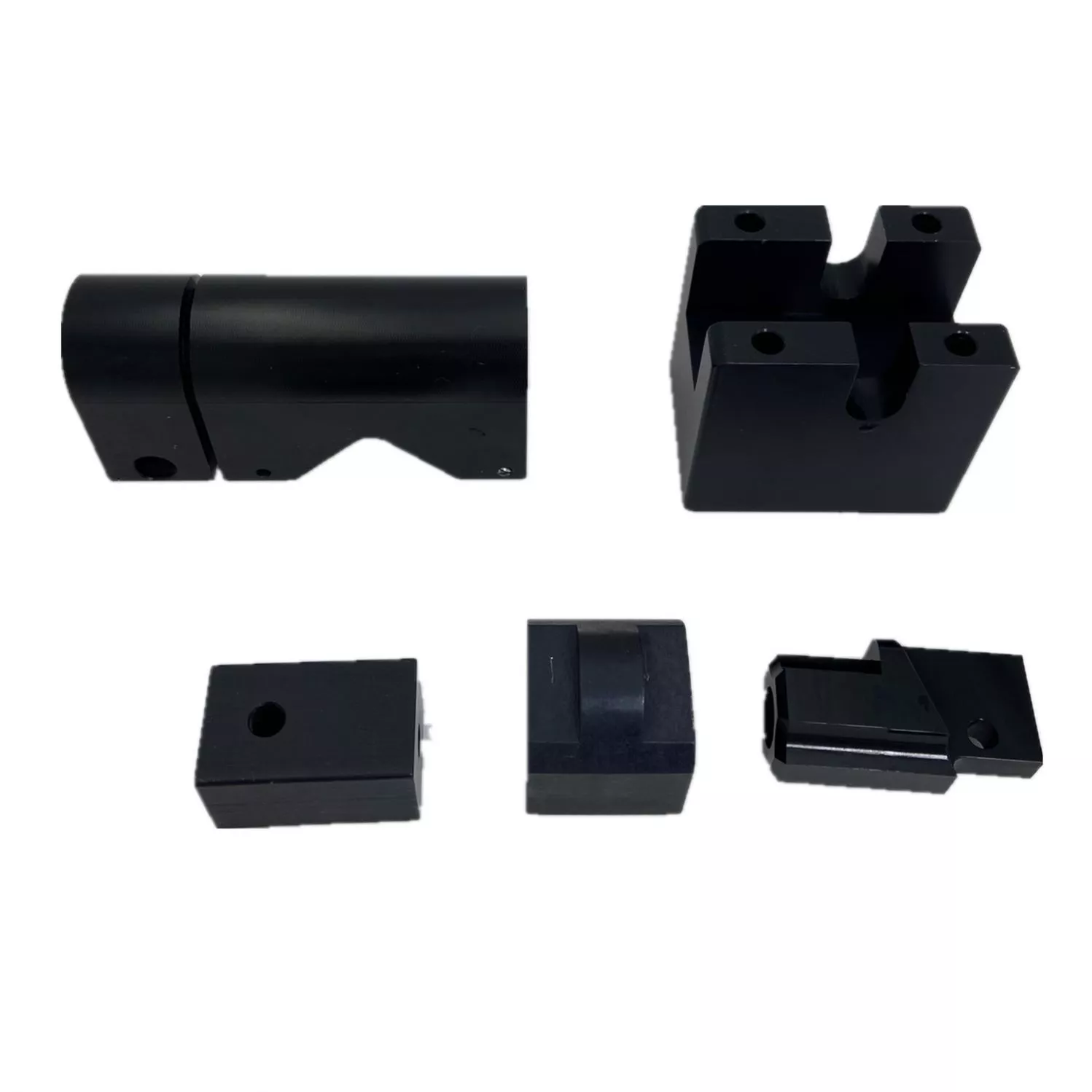
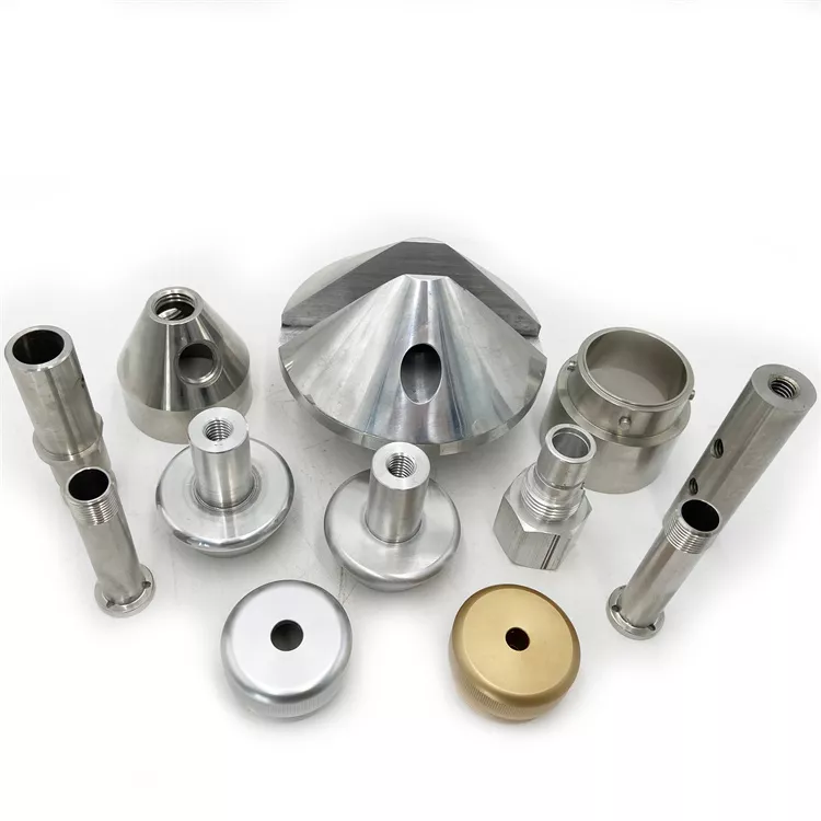
Custom OEM CNC Aluminum and Stainless Steel Machining Parts | Drawing Enquiries
-
CNC Machining or NotCnc MachiningTypeBroaching, DRILLING, Etching / Chemical Machining, Laser Machining, Milling, Other Machining Services, Rapid Prototyping, Turning, Wire EDM
-
Material CapabilitiesAluminum, Brass, Bronze, Copper, Hardened Metals, Precious Metals, Stainless Steel, Steel AlloysMicro Machining or NotMicro Machining
-
Model NumberDmetal-200122Surface treatmentSmooth
-
CertificationISO9001:2008MaterialAluminum Alloy
-
Surface finishAnodized/oxide etc /powder coatedSizeCustomized Size
-
Tolerance±0.1ToolingMade by ourself
-
Drawing Format2D/(PDF/CAD)3D(IGES/STEP)
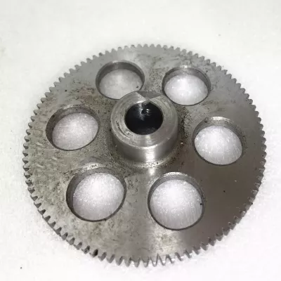
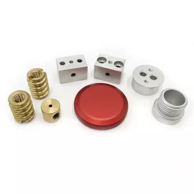
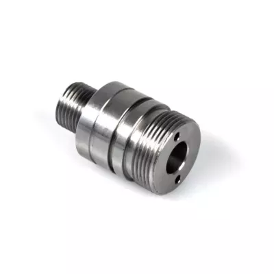
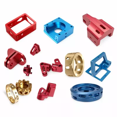
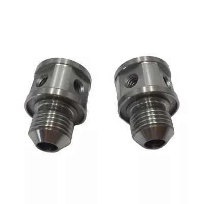
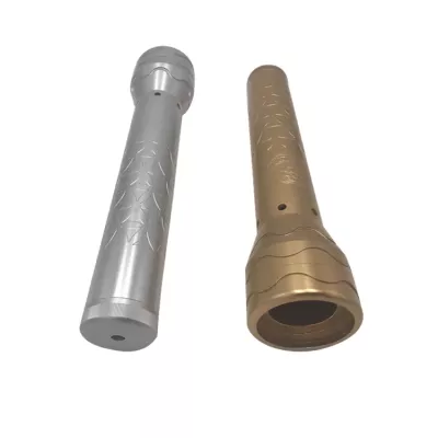
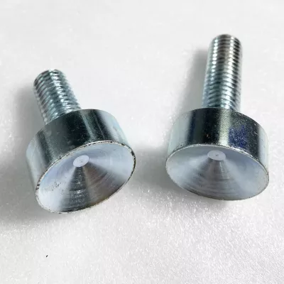
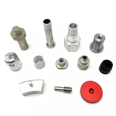
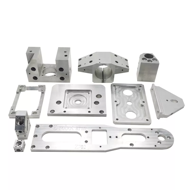
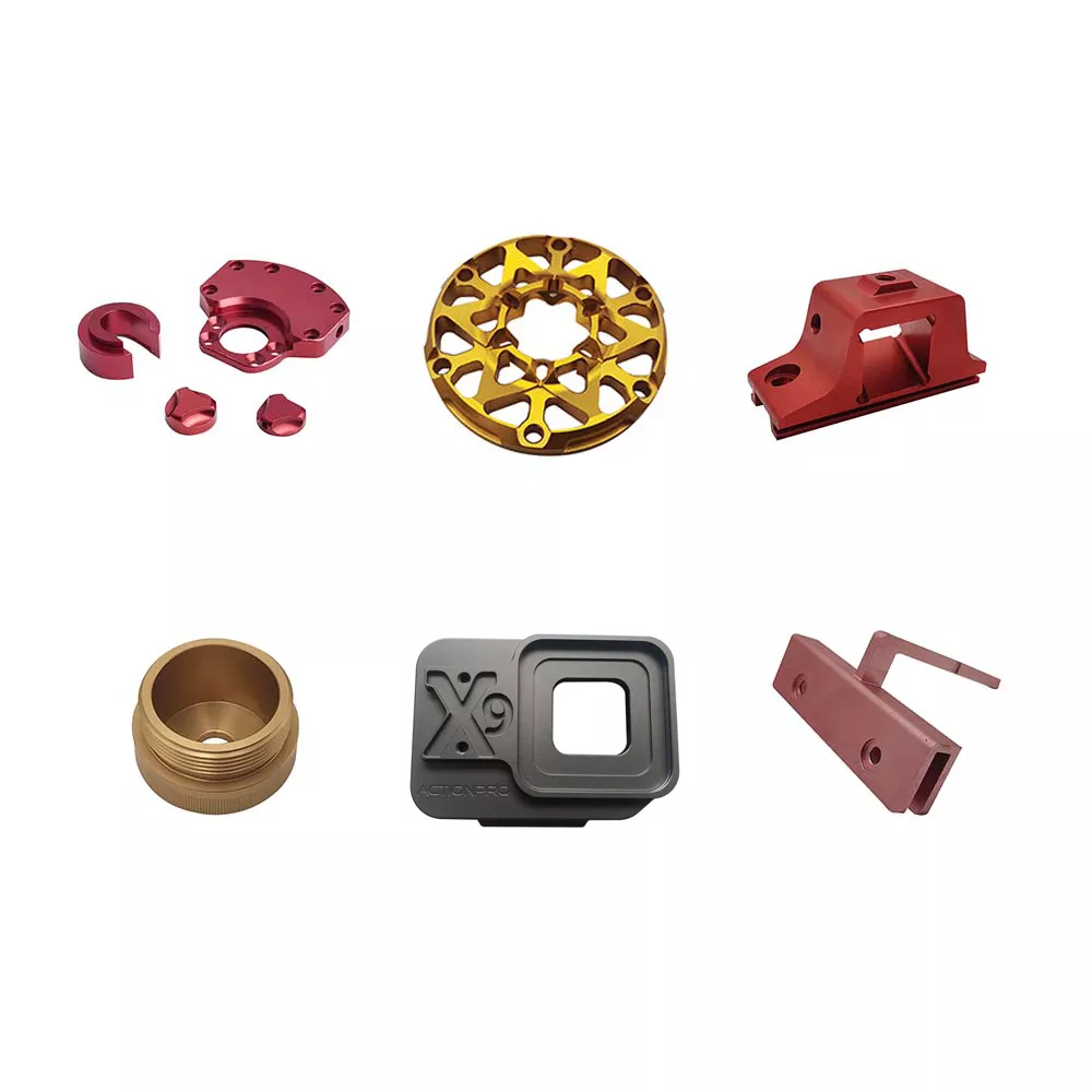
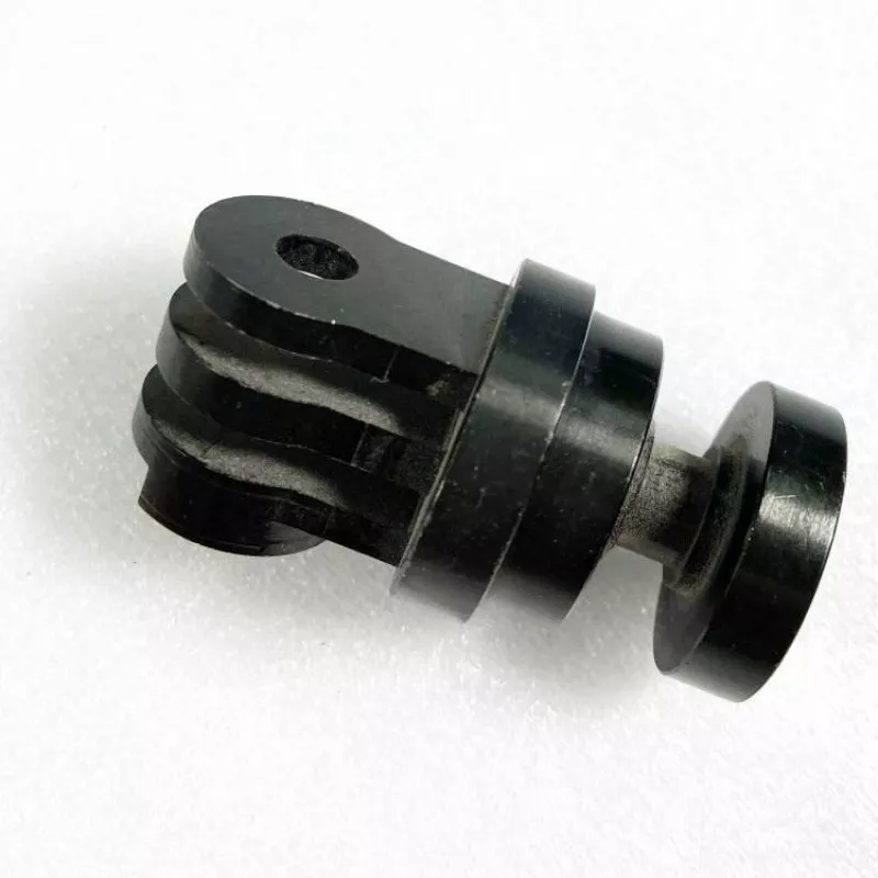
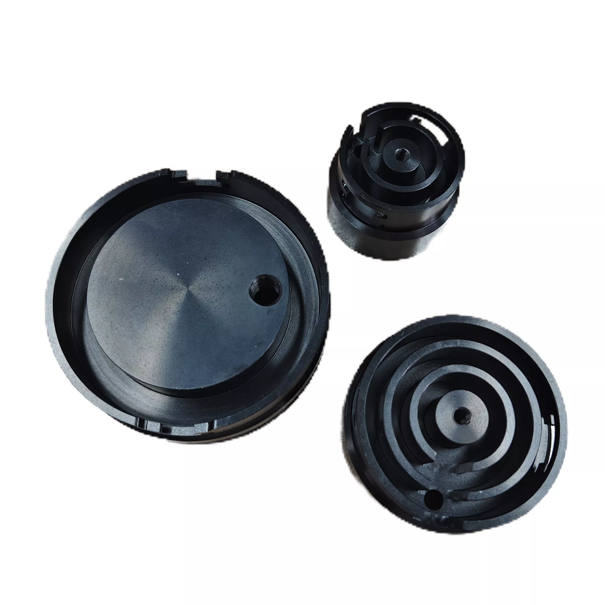
Give each custom CNC component its own drawing and material specification. The examples include tubes, flanged cylindrical pieces, a conical item, a threaded piece and round caps. An assortment image does not establish one shared drawing, alloy, finish or engineering function for all the items.
Organize the drawing and component schedule
Identify every required part with its drawing revision and quantity. The catalogue names 2D PDF or CAD and 3D IGES or STEP formats. Use the drawings to define dimensions, datums and acceptance requirements, with model data where it clarifies the actual geometry.
Locate bores, threads, flanges and mating faces from the references used by the assembly. Show the relationships that control fit and identify any special edge or surface requirements. The photograph does not define a thread standard, bore fit or a particular manufacturing setup.
Select the metal and secondary operations
Choose the actual aluminum or stainless-steel grade and required condition for each part. The title's material range and the aluminum-alloy table entry are sourcing directions, not evidence that one sample contains every listed metal. Agree the turning, milling, drilling or other operations needed by the chosen drawing.
Match finishing to the selected material and application. An anodizing or powder-coating menu does not specify the finish of every illustrated item. Mark contact surfaces and threads needing protection, and state whether dimensions are accepted before or after the agreed treatment.
Define precision through inspectable requirements
- Provide an individual part number, drawing and quantity.
- Select the actual material grade and condition.
- Locate mating dimensions, bores and threaded interfaces.
- Identify machining, finish and masking requirements.
- State feature-specific limits and inspection records.
The ±0.1 reference needs units and affected dimensions before it can govern acceptance; it is not a universal precision guarantee for the assortment. Historical certification or manufacturer wording does not replace current applicable evidence. Confirm the supplied scope and any application-specific documentation. A useful enquiry connects each selected part to one coherent material, machining and final inspection plan.