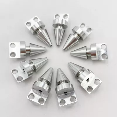
-
CNC Machining or NotCnc MachiningTypeBroaching, DRILLING, Etching / Chemical Machining, Laser Machining, Milling, Other Machining Services, Turning, Wire EDM, Rapid Prototyping
-
Material CapabilitiesAluminum, Brass, Bronze, Copper, Hardened Metals, Precious Metals, Stainless Steel, Steel Alloys, PlasticMicro Machining or NotMicro Machining
-
Model NumberS2212Machining3/4/5 Axis CNC Machining/ Gantry Machining Center
-
Surface treatmentAnodized/oxide etc /powder coated/polishing/grinding/paintingTolerance±0.02 or as your drawings requirements
-
ToolingMade by ourselfApplicationIndustry/Medical/Autospare
-
MaterialAluminum / Stainless Steel / Brass /Cooper/Zinc etc...ColorSilver / Black or as per your request
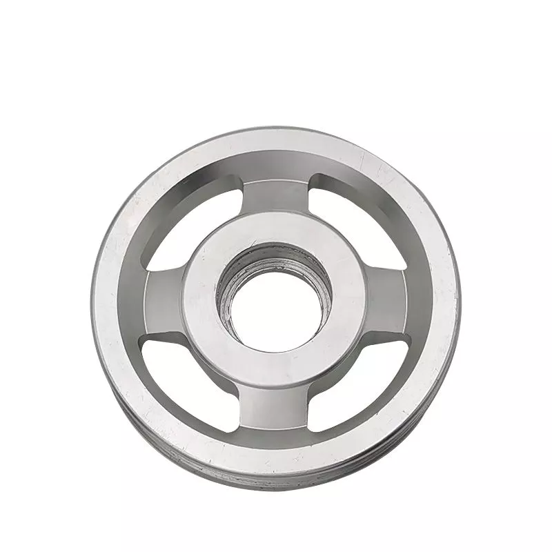
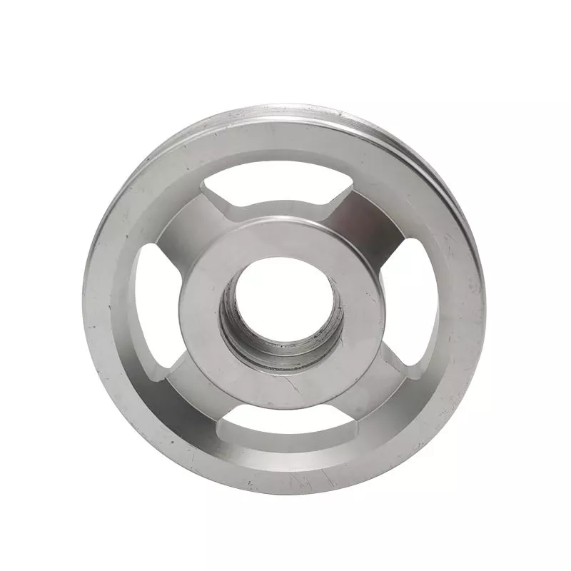
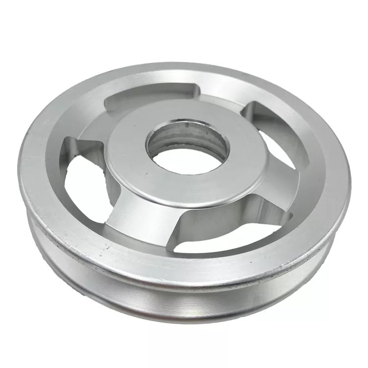
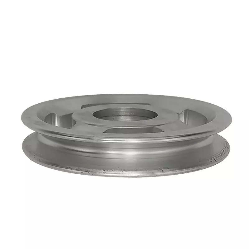
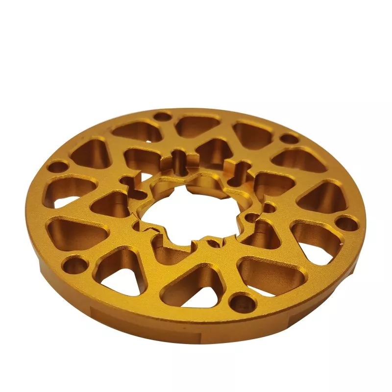
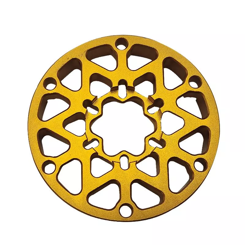
A windowed ring enquiry needs more than an outside diameter. The illustrated form joins a central hub to an outer rim with four radial webs, leaving four open windows. For an aluminum CNC turning and milling project, use those features to identify the drawing required, without assuming that the part is a pulley, a bearing component or a rated rotating assembly.
Establish the ring and bore references
Provide the drawing revision and identify the cylindrical surfaces that define the part. Dimension the outside rim, central bore, hub faces and axial thickness. Locate the windows and webs relative to those references so that the turning and milling requirements describe one consistent geometry.
If the central opening requires a thread, state its standard, size and acceptance requirements explicitly. The thread-like lines visible in the photograph do not establish those details. Identify mating components and the clearances or contact faces that determine fit.
Choose operations and the supplied finish
Select the actual aluminum alloy and material condition. Define the turned diameters and faces separately from the milled windows or other secondary features. General machine-axis and gantry descriptions do not specify the setup or dimensional capability for this particular ring.
- Mark the cylindrical references, hub and rim dimensions.
- Locate all windows and webs from common datums.
- Specify any thread and its inspection requirements.
- Identify finish, masking and dimensions in the final condition.
- State the intended assembly and any required operating-duty evidence.
Make dimensional acceptance explicit
Put units, tolerances and inspection criteria on the component drawing. A general precision label or a catalogue tolerance without defined units cannot replace feature-specific requirements. Where surface treatment affects a bore or mating face, agree whether the dimension applies before or after that operation.
State the intended assembly and service conditions with the quantity required. Operating loads, speed or equipment qualification need evidence applicable to the actual design. A useful ring enquiry connects its rim, bore and window geometry to the finished interfaces that must be accepted.