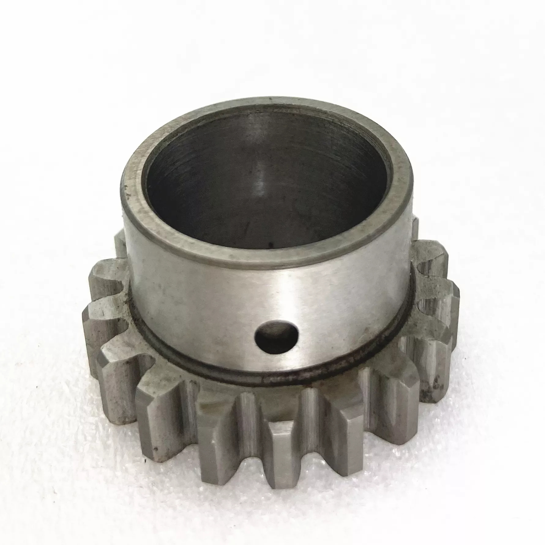
Custom CNC Machining Aluminum Spur Gear Transmission Parts | Precision Drawing Enquiries
-
CNC Machining or NotCnc MachiningTypeBroaching, DRILLING, Etching / Chemical Machining, Laser Machining, Milling, Other Machining Services, Rapid Prototyping, Turning, Wire EDM
-
Material CapabilitiesAluminum, Brass, Bronze, Copper, Hardened Metals, Precious Metals, Stainless Steel, Steel AlloysMicro Machining or NotMicro Machining
-
Model NumberDmetal-200405Surface treatmentSmooth
-
CertificationISO9001:2008MaterialAluminum Alloy
-
Surface finishAnodized/oxide etc /powder coatedSizeCustomized Size
-
Tolerance±0.1ToolingMade by ourself
-
Drawing Format2D/(PDF/CAD)3D(IGES/STEP)
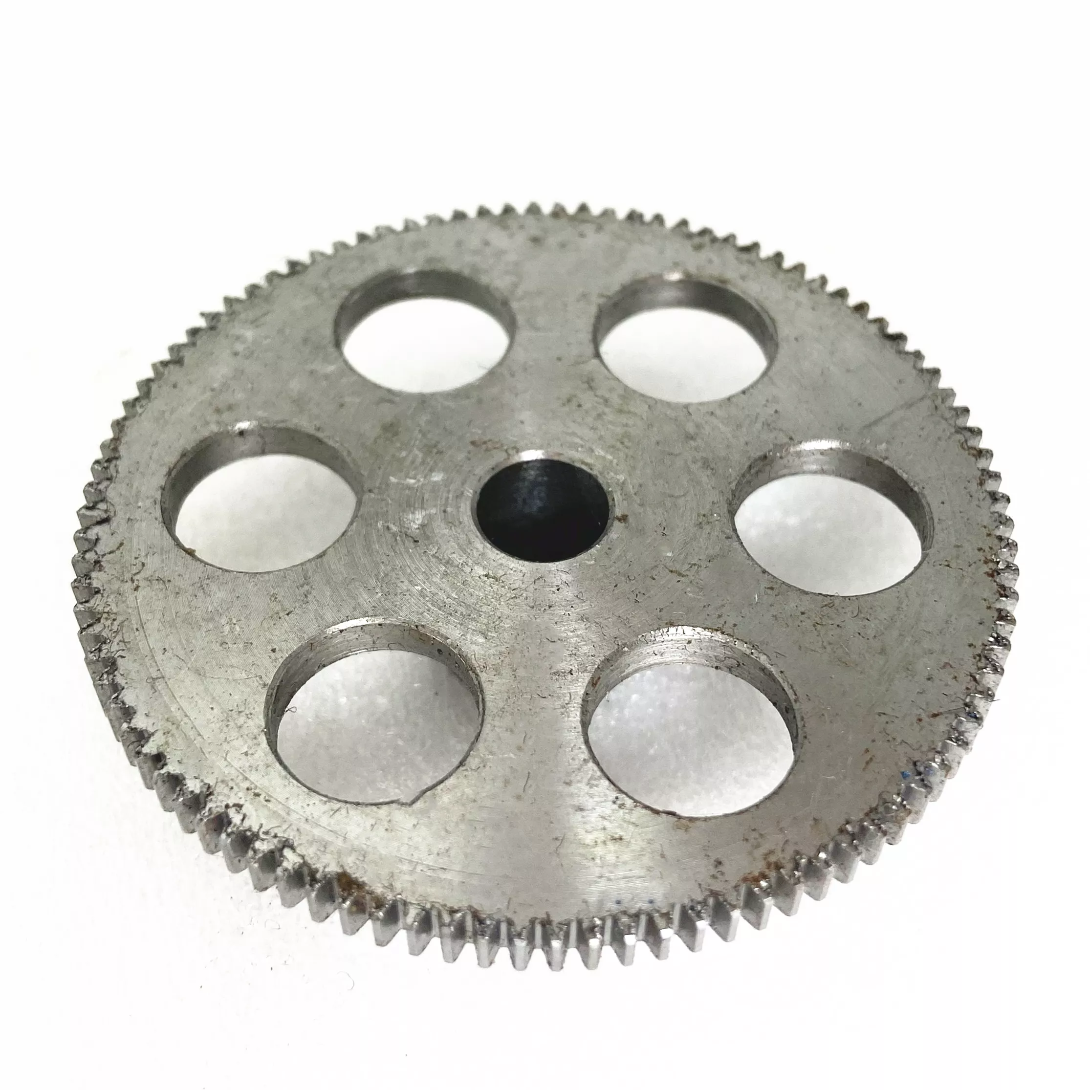
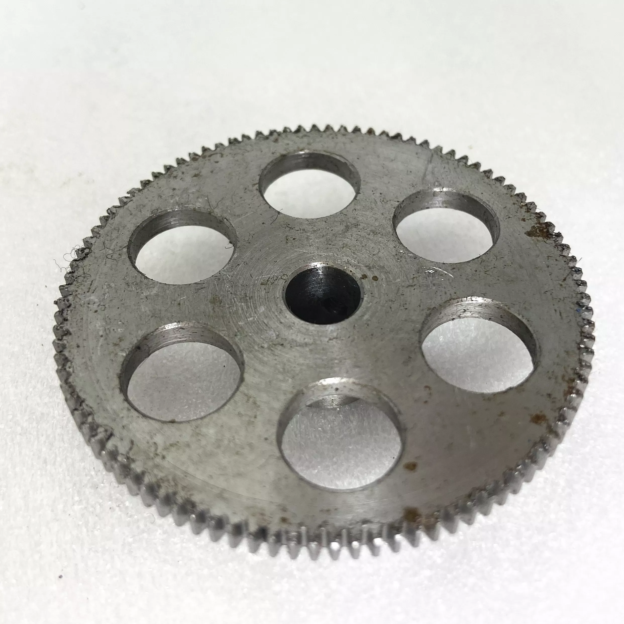
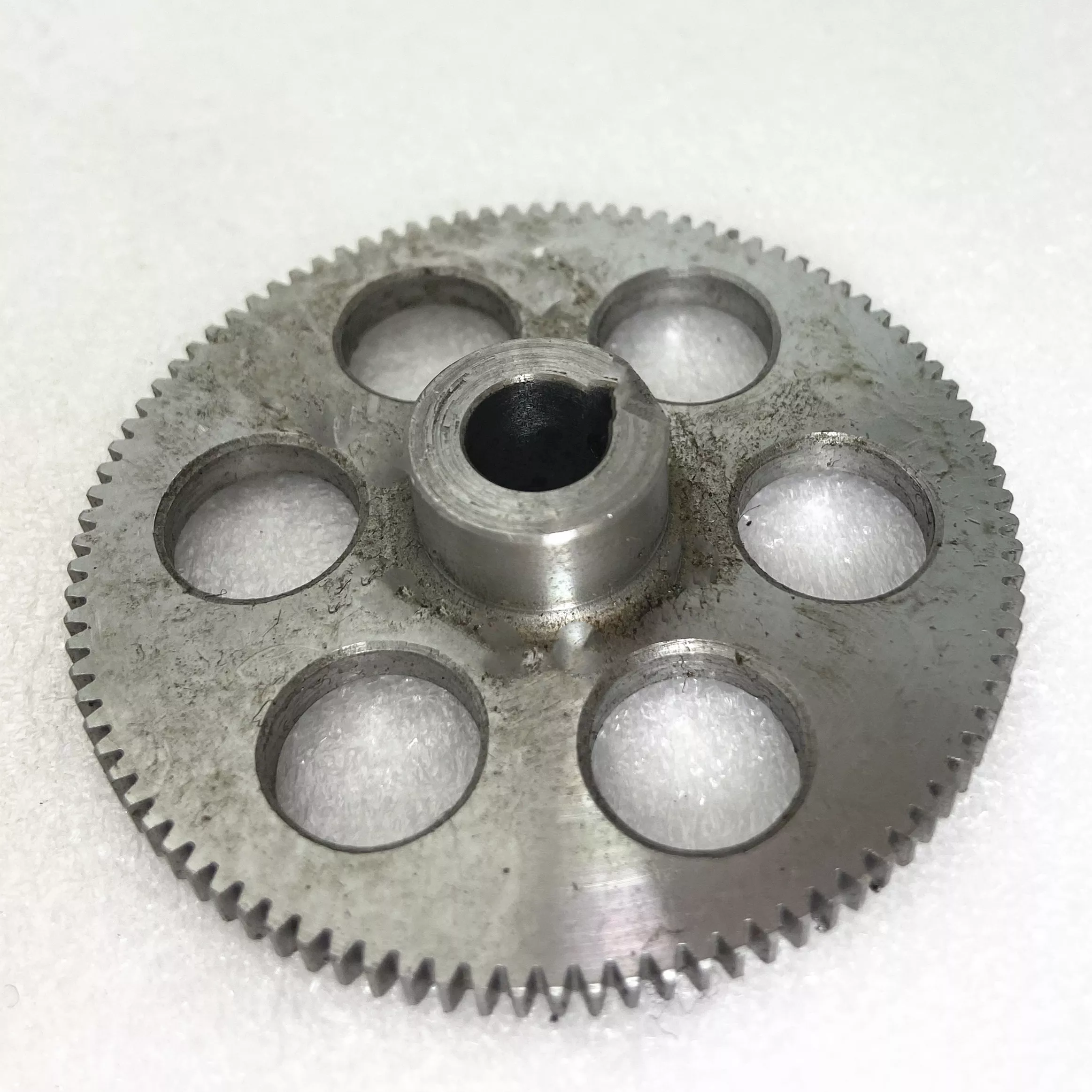
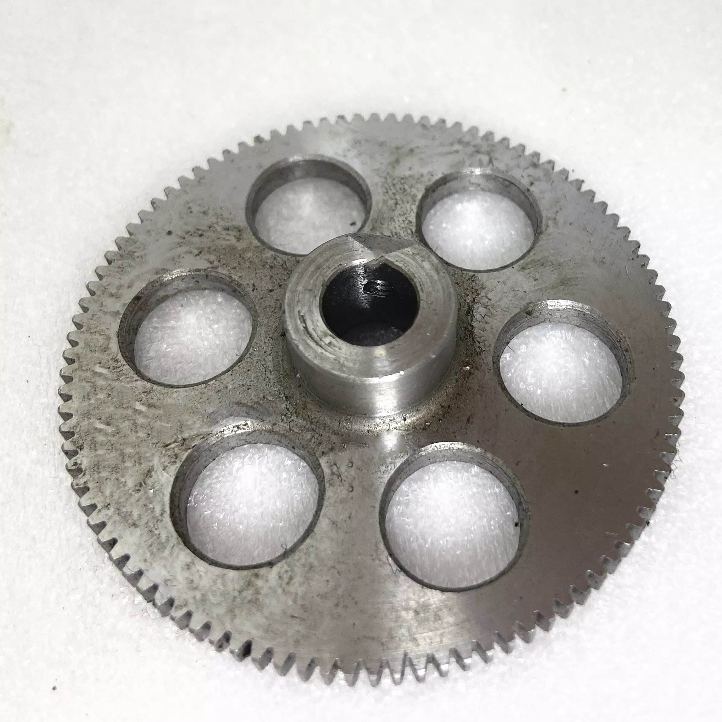
Specify the transmission gear from its tooth geometry and mating requirements. The example is a fine-toothed circular part with a raised central hub, a central bore and six large openings through the web. Its appearance identifies a gear-like component, but does not establish its actual alloy, dimensions or operating capacity.
Define the tooth system and mating gear
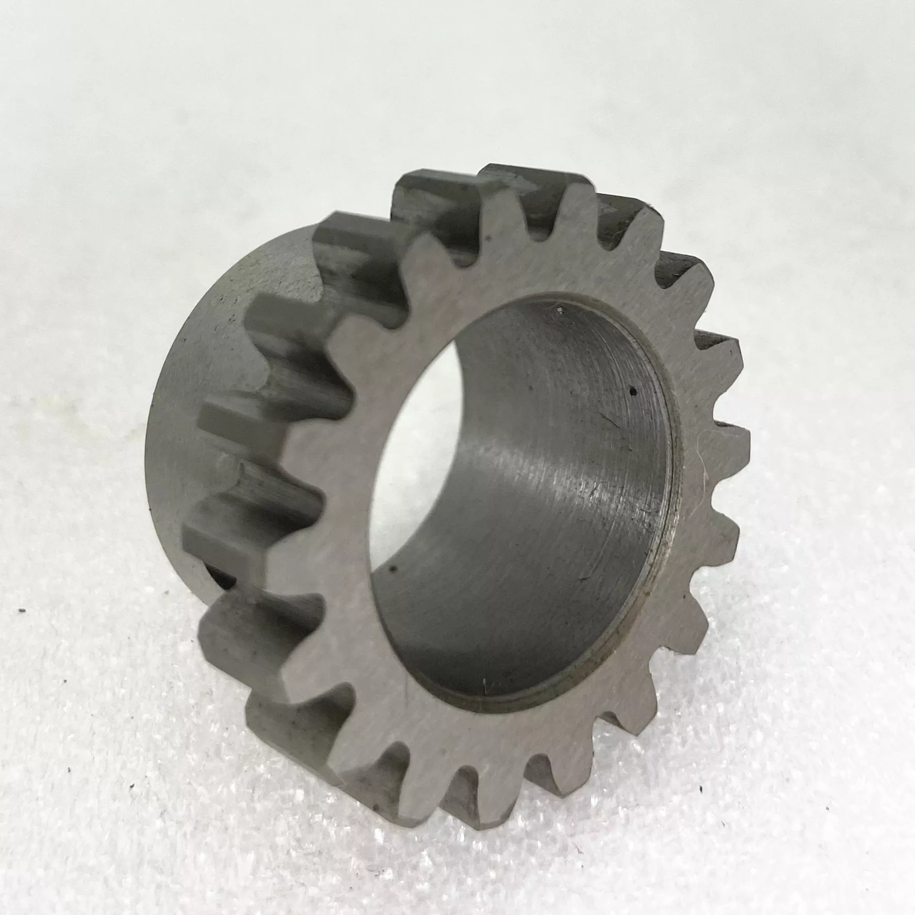
Provide the controlled gear drawing and the information that defines the teeth, including the required count, size convention, profile and accuracy criteria. Include the mating component or assembly details that determine engagement. The image does not establish those values, and a general precision label cannot replace a gear specification.
- Provide the complete tooth and mating-gear requirements.
- Dimension the bore, hub and mounting references.
- Specify the web openings and remaining component geometry.
- Select actual material, condition and finishing requirements.
- Define dimensional and application-specific acceptance evidence.
Locate the gear from the shaft interface
Dimension the bore and hub from the assembly datums and identify the method by which the component interfaces with adjoining parts. Mark any threads, mounting details or other features required by the actual design. The photograph does not prove a shaft-fit standard or establish that every visible opening has a particular function.
Select the aluminum alloy and condition required by the order. Agree the actual tooth-making and secondary-machining route rather than assuming that every listed CNC service applies. Identify any finish or treatment needed for the selected material, with the surfaces on which dimensional acceptance is required.
Make the intended duty part of acceptance
Provide the operating context and the load, speed or other requirements relevant to the application. No torque rating, hardness, service life or transmission compatibility is established by the picture. The ±0.1 reference needs units and affected features; it is not a complete tooth-accuracy or bore-fit specification. Use the listed drawing formats to connect the actual gear geometry to clear inspection records and any required application evidence. Confirm quantities and supplied scope so the proposed part can be assessed against the same requirements used for the enquiry.