Custom CNC Aluminium Machining Parts | Rounded-End Drilled Component Enquiries
-
CNC Machining or NotCnc MachiningTypeBroaching, DRILLING, Etching / Chemical Machining, Laser Machining, Milling, Other Machining Services, Turning, Wire EDM, Rapid Prototyping
-
Material CapabilitiesAluminum, Brass, Bronze, Copper, Hardened Metals, Precious Metals, Stainless Steel, Steel AlloysMicro Machining or NotMicro Machining
-
Model NumberS2403Product namecustom cnc machined parts
-
Surface treatmentanodizing/powder coating/painting/polishing / chrome plating etcMaterialAluminum Alloy
-
Drawing Format2D/(PDF/CAD)3D(IGES/STEP)MOQ10 pcs
-
Materials Avaliablealuminum/ stainsteel steel/ brass/ zincCertificationISO9001:2015
-
ProcessCnc Machining+deburrs +surface treatmentLogoAccept Custom Logo
-
Tolerance0.01mm
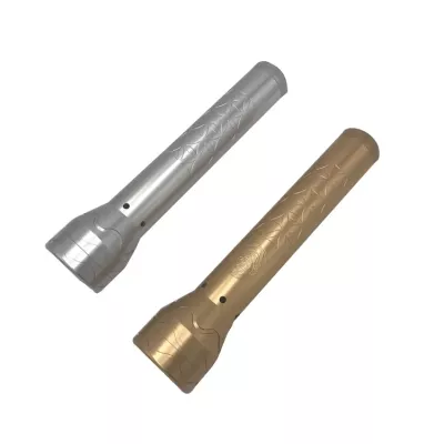
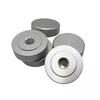
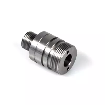
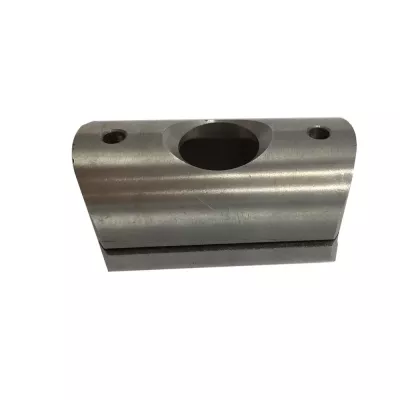
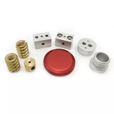
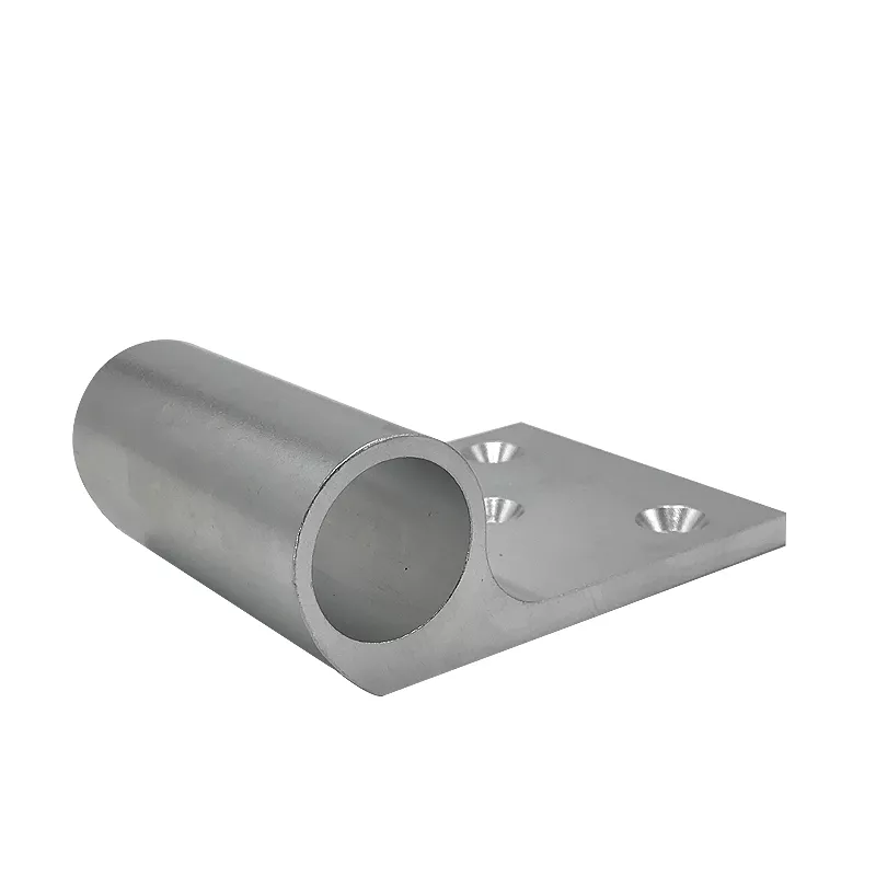
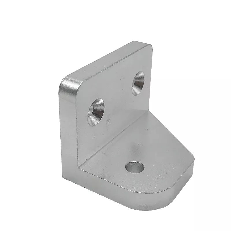
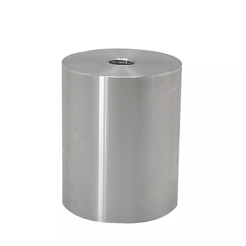
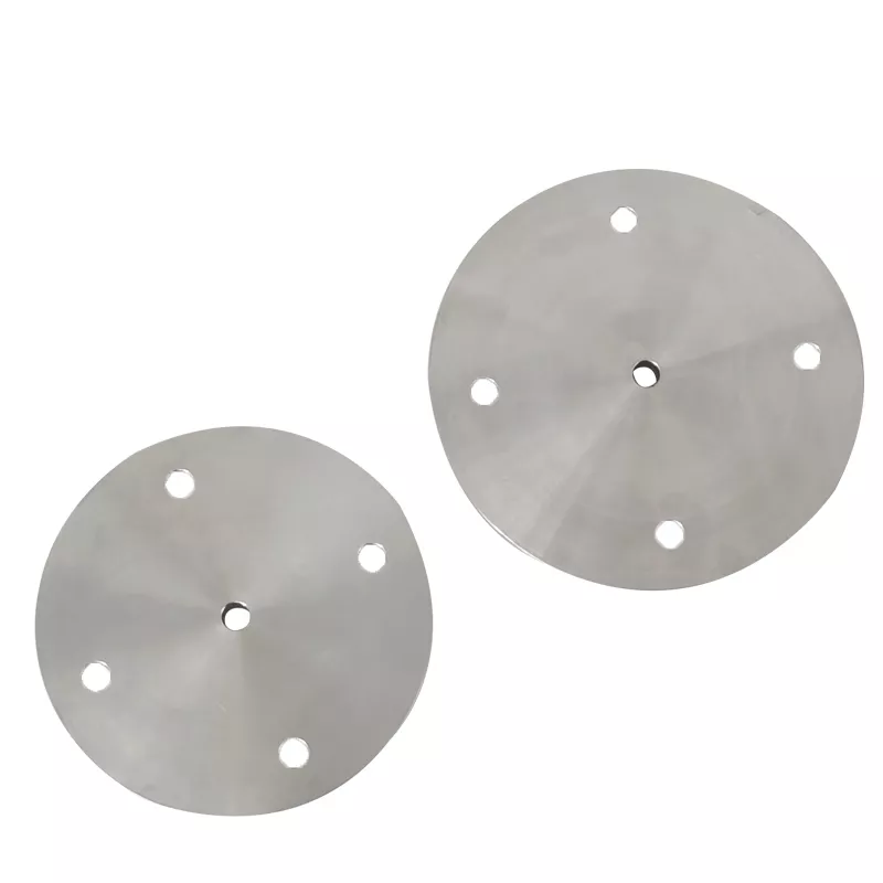
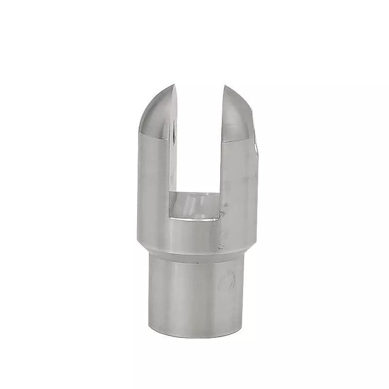
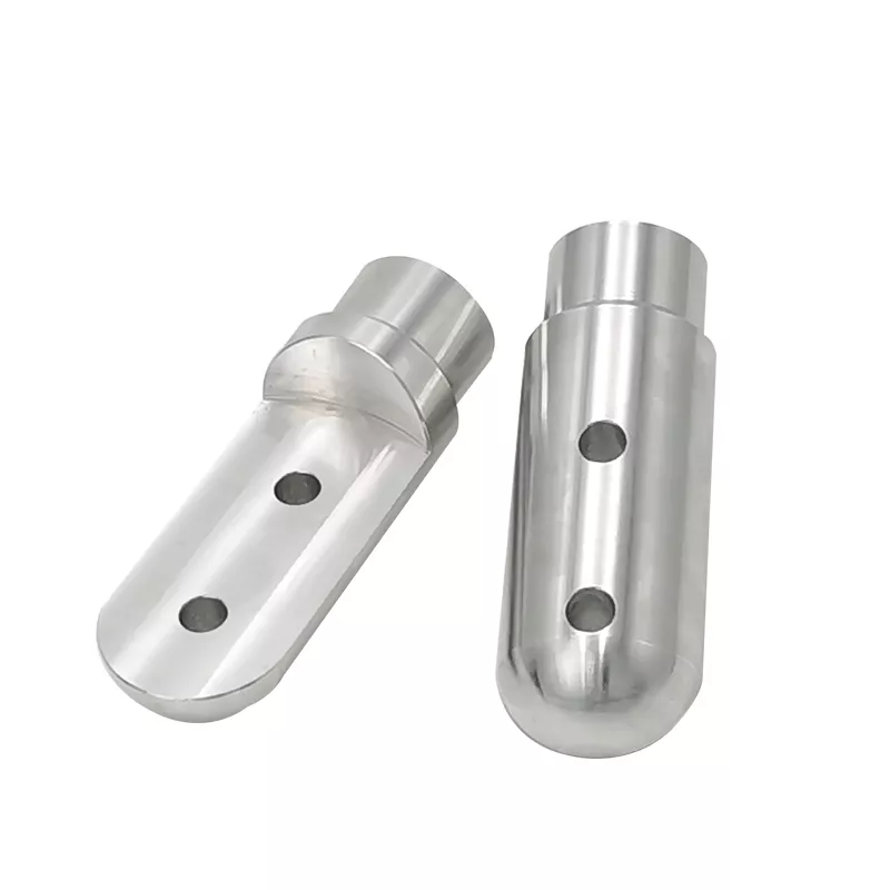
Rounded ends, stepped cylindrical sections and cross holes define the visible examples in this custom CNC aluminium machining enquiry. Identify the mating assembly and the actual part drawing before selecting the component. The photograph does not establish its operating function, material grade or compatibility with a particular mechanism.
Relate the cross holes to the turned references
Provide the drawing revision, quantities and required alloy. Dimension the stepped diameters, shoulders and rounded end, then locate each cross hole from the references used by the assembly. Identify flat regions or contact faces that affect orientation and fit.
Specify hole sizes, positional requirements and any mating clearances. A view showing two holes does not define their dimensions or the tolerances between them. Include section views where the drawing needs to explain details that are hidden from the exterior photograph.
Scope turning, secondary machining and deburring
Define the turned profile separately from milling of flats or drilling of cross holes. The listed process combines CNC machining, deburring and surface treatment; identify what is required for the actual component rather than assuming every catalogue operation is needed.
PDF/CAD and IGES/STEP inputs are listed. Select the aluminum alloy, material condition and treatment. Anodizing, powder coating, painting, polishing and chrome plating appear as general options, but the finish must be chosen for the actual material, contact surfaces and service conditions.
Agree the supplied-component acceptance
- Identify the mating assembly and dimensional references.
- Define shoulders, rounded end, flats and cross holes.
- Select material, machining, deburring and finish.
- Specify controlled features and required inspection records.
- State the actual mechanism and application acceptance requirements.
If the catalogue's 0.01 mm reference is requested, identify the particular dimension, tolerance convention and inspection method. It does not establish that value for every feature. Specify dimensions after treatment where finish affects fit. Appearance and general ISO wording do not prove coating performance, current certification or store manufacturer identity; use applicable evidence when those requirements affect selection.