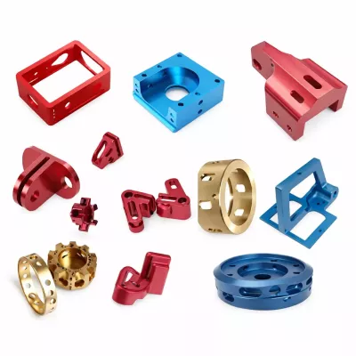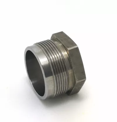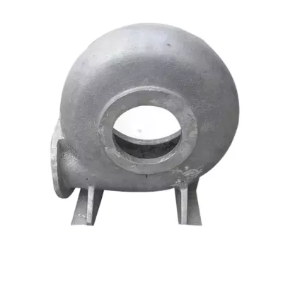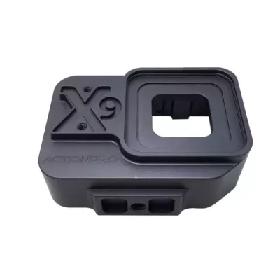
Custom Precision CNC Aluminum Milling Parts with Anodizing | Drawing Enquiries
-
CNC Machining or NotCnc MachiningTypeBroaching, DRILLING, Etching / Chemical Machining, Laser Machining, Milling, Other Machining Services, Rapid Prototyping, Turning, Wire EDM
-
Material CapabilitiesAluminum, Brass, Bronze, Copper, Hardened Metals, Precious Metals, Stainless Steel, Steel AlloysMicro Machining or NotMicro Machining
-
Model NumberDM-CNCSurface treatmentAnodizing
-
CertificationISO9001:2008MaterialAluminum Alloy
-
Surface finishAnodized/oxide etc /powder coatedSizeCustomized Size
-
Tolerance±0.1ToolingMade by ourself
-
Drawing Format2D/(PDF/CAD)3D(IGES/STEP)MOQ100pcs
-
Materials Avaliablealuminum/ stainsteel steel/ brass/ zinc
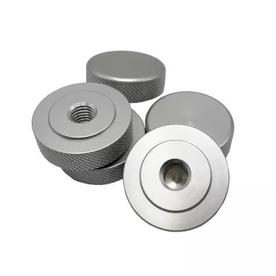
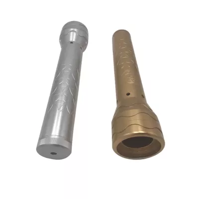
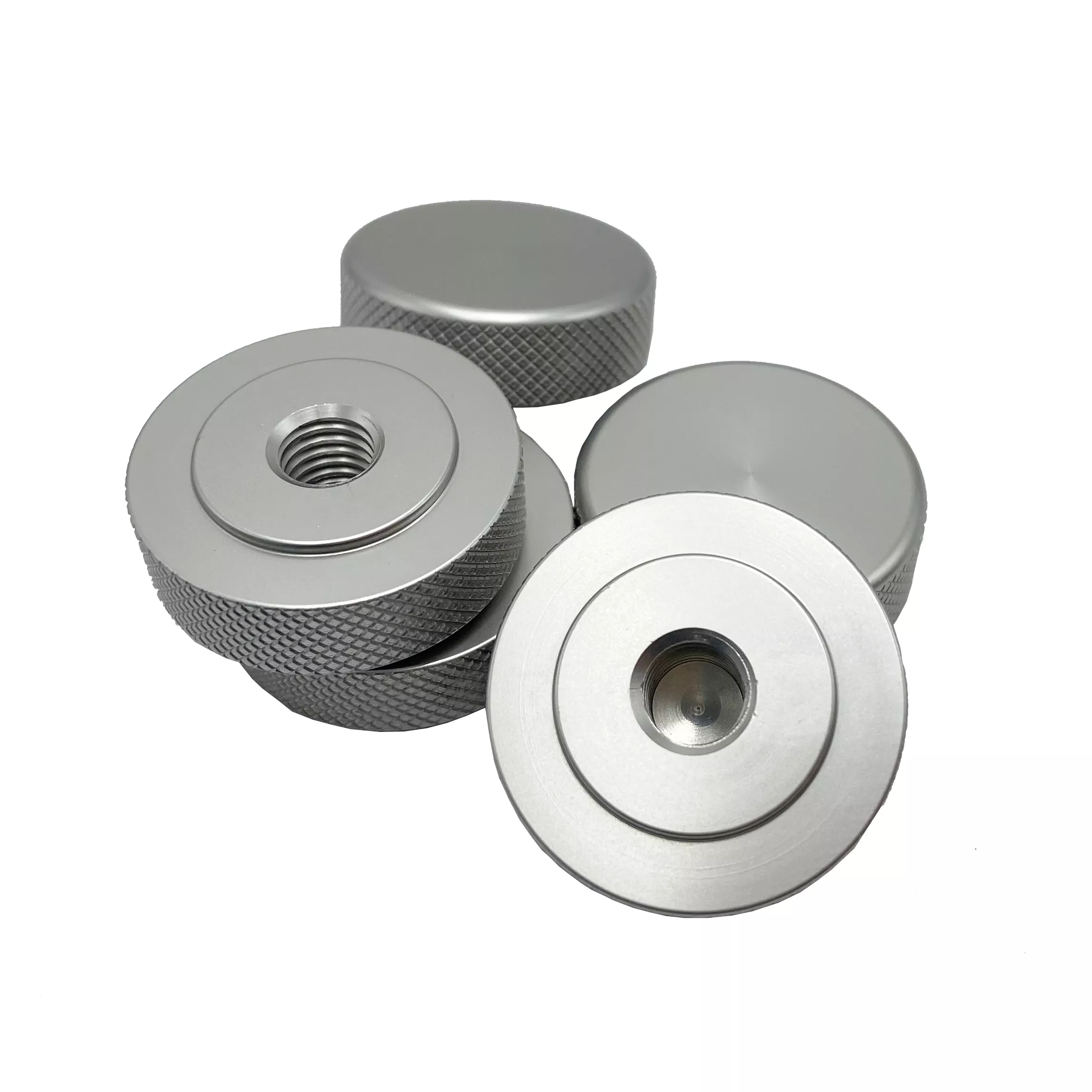
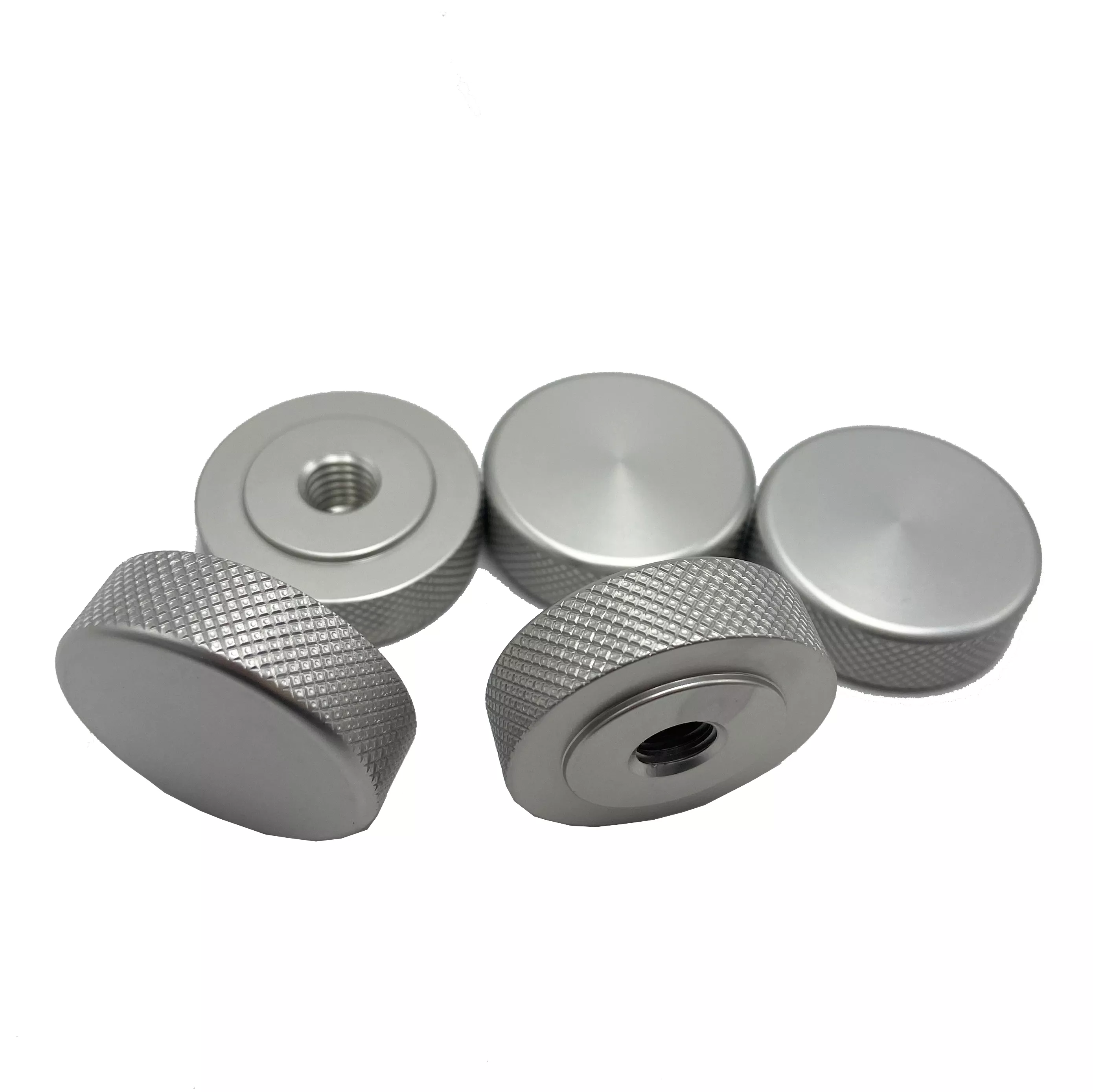
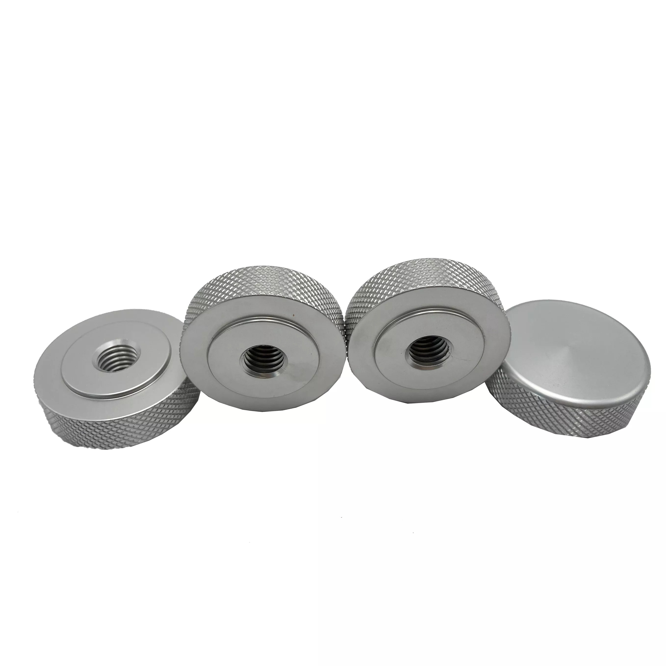
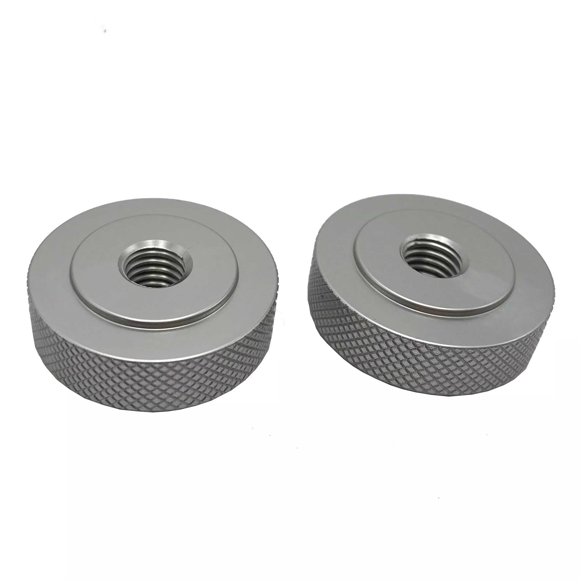
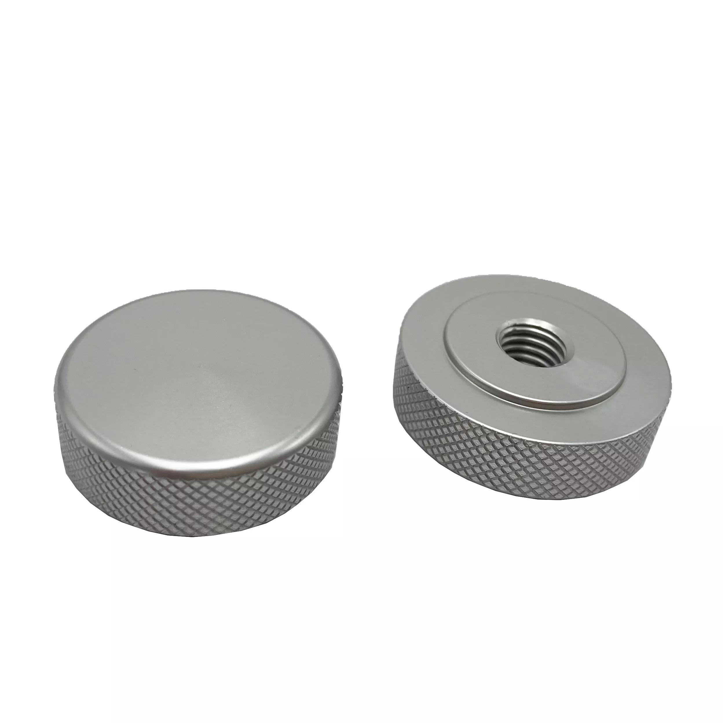
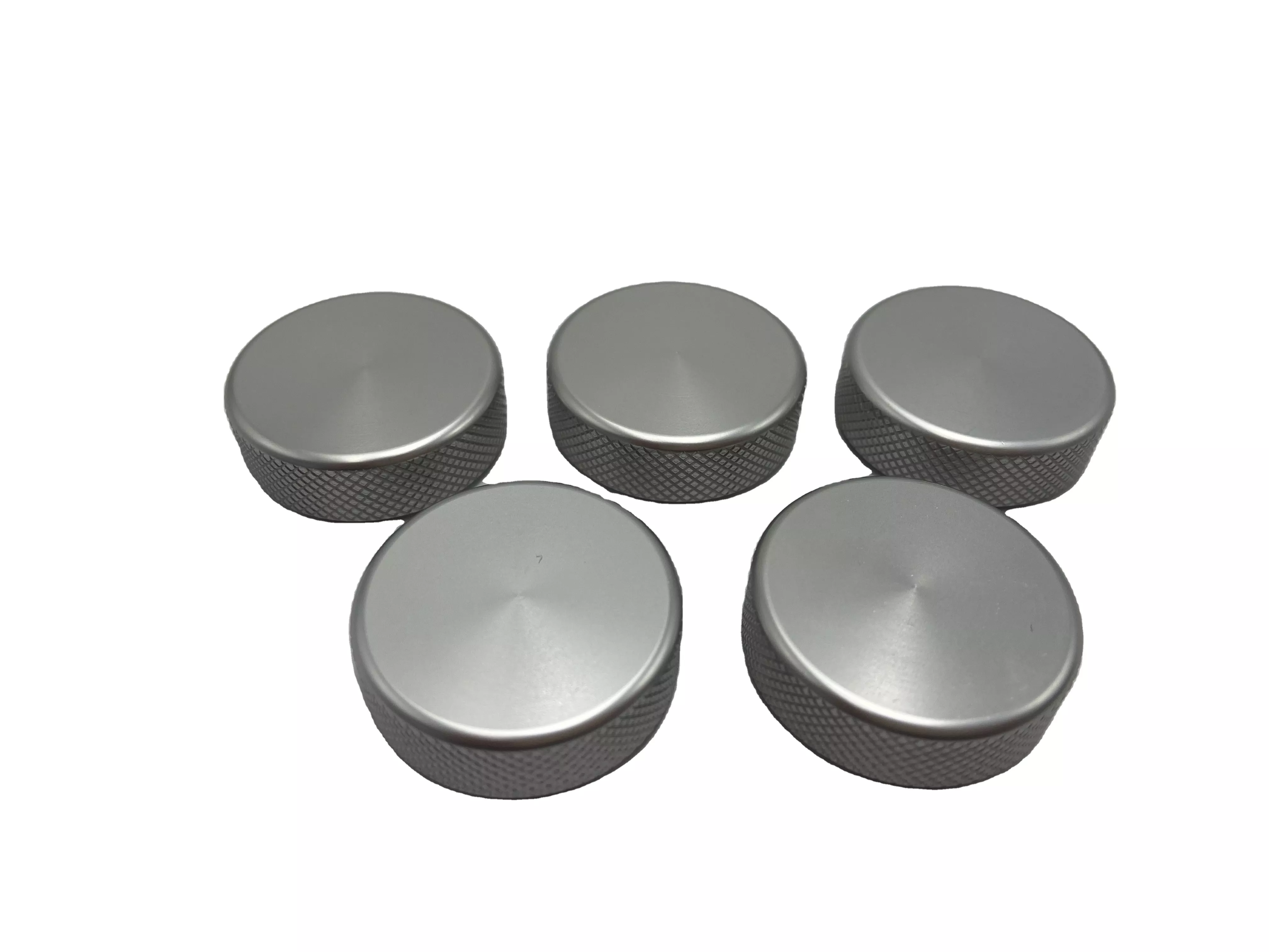
Define the aluminum component and its mating arrangement before selecting a milling and finishing scope. The examples are round cap-like parts with knurled edges, including threaded or recessed central openings and a plain upper face. Their appearance does not establish a thread standard, actual alloy or anodized condition.
Start with the cap and mating interface
Provide the outside diameter, thickness and the geometry of the central opening. Locate any thread or recess from the drawing references and include the mating component where it controls fit. Identify which items are individual components and which, if any, belong to an assembled supply.
- Provide the cap drawing and mating-interface specification.
- Select the actual aluminum grade and condition.
- Define the opening, thread and knurled-edge geometry.
- Specify anodizing, color and fit-sensitive masking.
- State finished dimensional and appearance acceptance.
Agree the machining and anodizing plan
Identify the surfaces requiring turning, milling, drilling or other secondary work. A milling-focused title does not mean that every illustrated surface uses the same process. Specify the actual edge pattern and its acceptance rather than assuming a grip-performance result from a knurled appearance.
Choose the anodized finish required by the selected material and application. Mark threads, contact faces or other interfaces where treatment affects fit. Define the condition in which those surfaces are measured and identify any supporting finish records needed for the order.
Inspect the selected component against the drawing
The ±0.1 field is a reference requiring units, affected features and measurement criteria; it is not a universal precision guarantee for the whole cap. Provide any application-specific acceptance requirements, without inferring a sealing or other functional rating from the component shape. Historical certification and minimum-quantity entries do not replace current applicable evidence and agreed supply terms. Use the listed drawing formats to connect the actual geometry to its material, machining and final-condition inspection plan. Confirm quantities and included parts so that the delivered scope matches the component specification used for the enquiry.