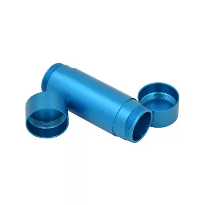
-
CNC Machining or NotCnc MachiningTypeBroaching, DRILLING, Etching / Chemical Machining, Laser Machining, Milling, Other Machining Services, Turning, Wire EDM, Rapid Prototyping
-
Material CapabilitiesAluminum, Brass, Bronze, Copper, Hardened Metals, Precious Metals, Stainless Steel, Steel AlloysMicro Machining or NotMicro Machining
-
Model NumberDmetal-200444Surface treatmentSmooth
-
CertificationISO9001:2008MaterialAluminum Alloy
-
Surface finishAnodized/oxide etc /powder coatedSizeCustomized Size
-
Tolerance±0.1ToolingMade by ourself
-
Drawing Format2D/(PDF/CAD)3D(IGES/STEP)
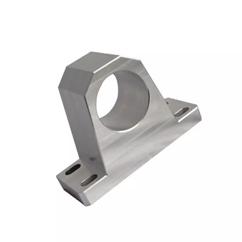
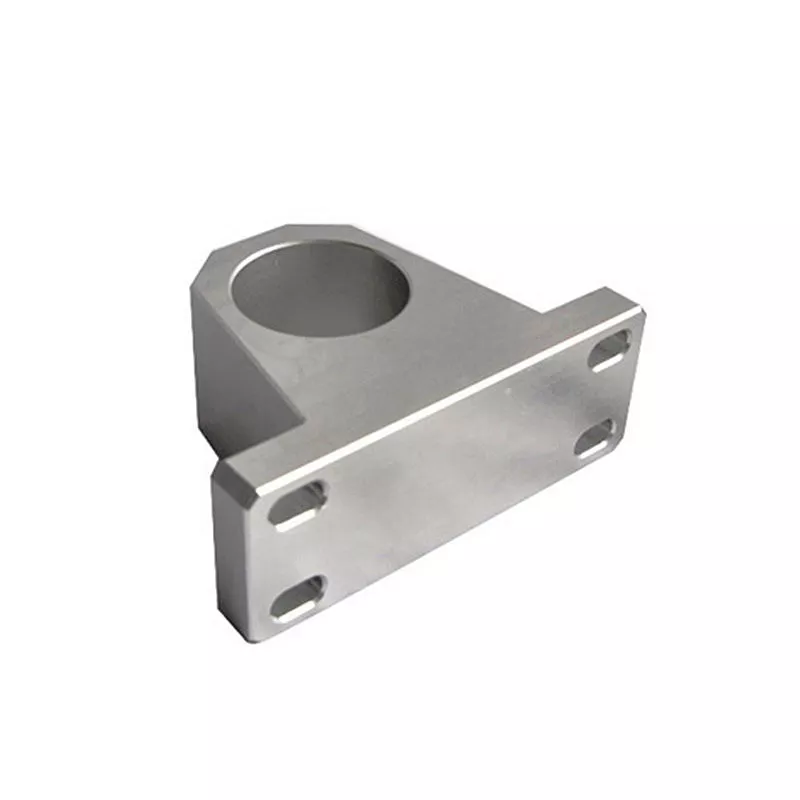
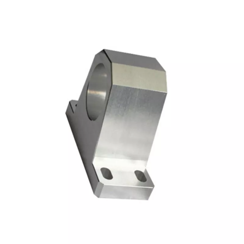
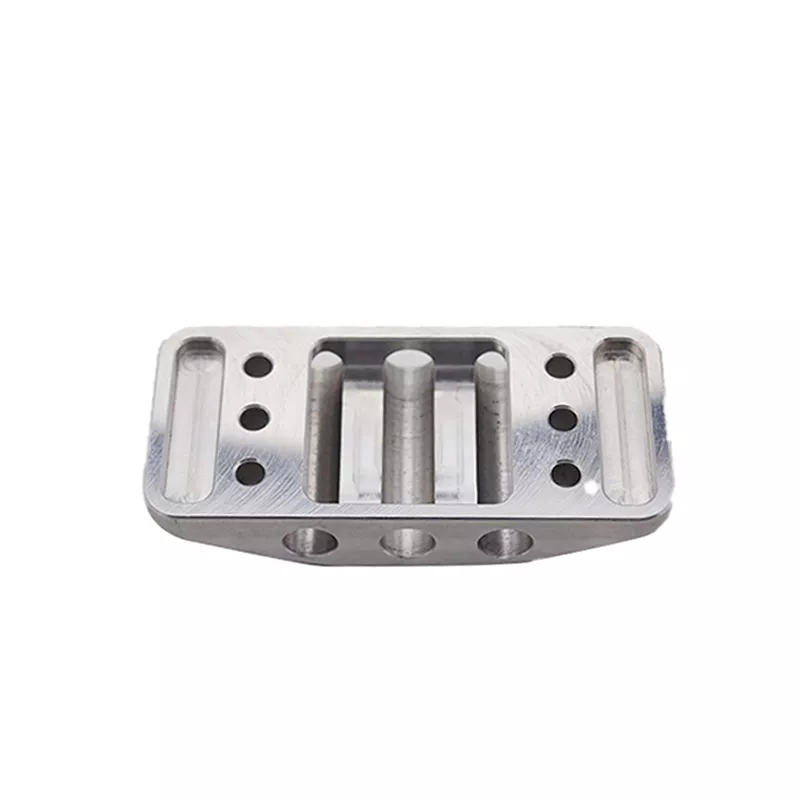
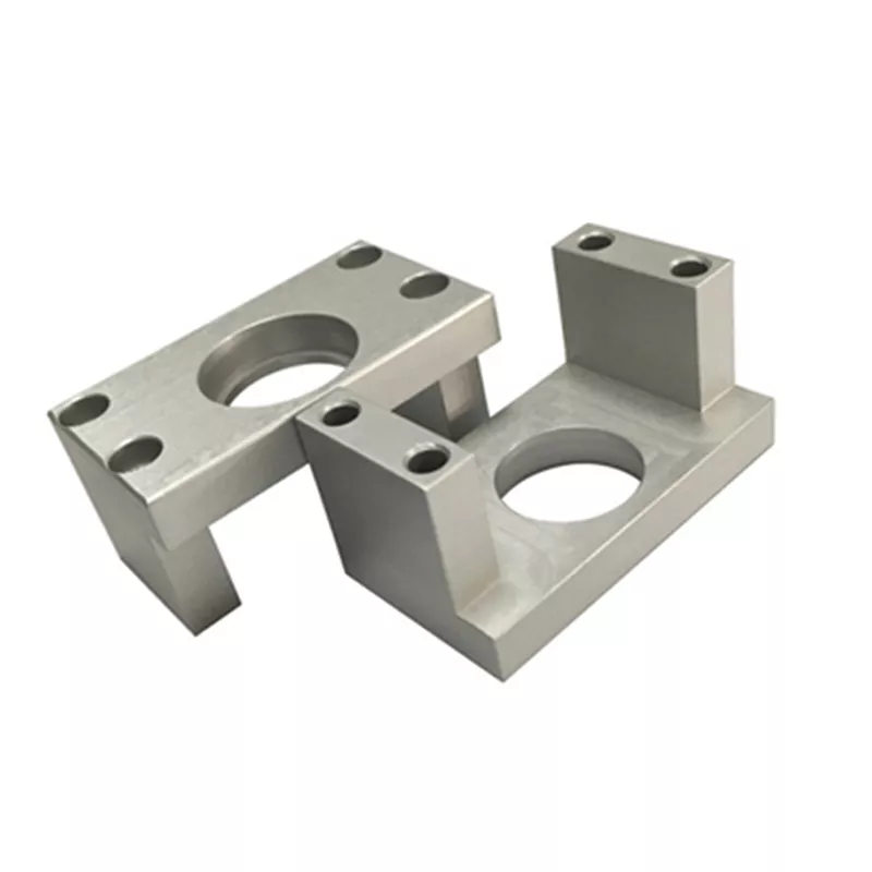
A large circular opening and elongated base slots are the main interfaces of the illustrated support-like component. For a custom aluminum CNC milling enquiry, define how those features meet the mating assembly. The photograph does not identify a bearing standard, a shaft-support rating or a complete clamping arrangement.
Locate the bore above the mounting base
Provide the drawing revision and specify the circular opening, upright thickness and base geometry. Relate the opening center and orientation to the base contact surface and the mounting references. Include the dimensions that control the actual assembly rather than interpreting the outside shape as an equipment standard.
Dimension the elongated slots, their positions and the available fastener clearance. If adjustment, clamping or another function is required, describe it explicitly. A visible opening or edge feature is not sufficient evidence of the required movement, retention or load capacity.
Bore masking and anodizing dimensions
Select the aluminum alloy, material condition and requested surface finish. Anodizing is a listed enquiry direction, with oxide and powder-coated alternatives also present in the general information. Surface appearance does not establish which process, thickness or coating performance applies to the actual order.
Identify bore or mounting surfaces that require masking, finish protection or dimensional inspection after treatment. State whether the supplied-condition dimensions include the coating. These decisions should be made alongside the mating-part requirements, especially where a finished bore or contact face determines fit.
Submit the support-component requirements
- Provide PDF/CAD dimensions and an IGES/STEP model where available.
- Identify the alloy, drawing revision and quantities.
- Define bore-to-base relationships and mounting slots.
- Specify finish, controlled units and inspection criteria.
- Include mating-part fit and any required service-load criteria.
The historical tolerance reference has no unit and is not a fixed machining guarantee. Require acceptance appropriate to the component and its service conditions. General tooling or ISO9001:2008 wording does not establish current store manufacturer identity, certification or qualification of the support for a particular operating load.