Custom Sheet Metal Fabrication and Stamping Kit Parts | Articulated Plate Components
-
Model NumberS2407RMaterial CapabilitiesSteel/Aluminum/copper/Stainless Steel 316/brass
-
ApplicationMachinery/Industry/Home/AutomotiveEquipmentCNC Bending/Stamping Machine/Laser Marking
-
ProcessLaser Cutting Bending StampingKeywordSheet metal fabricating part
-
Surface treatmentPainting\Powder Coating\Plating\PolishingDrawing format2D/3D/CAD/DWG//STEP/PDF/IGS
-
CertificateISO9001/TS16949LogoAccept Customized Logo
-
TechnologyStamping+drilling+assembly
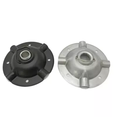
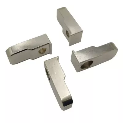
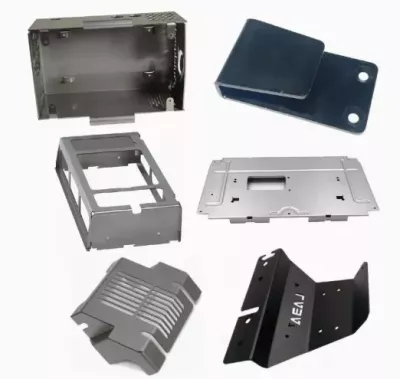
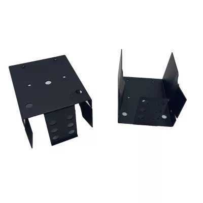
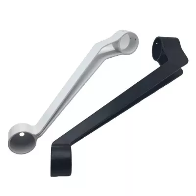
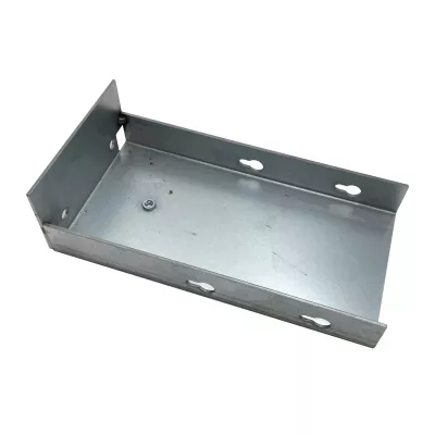
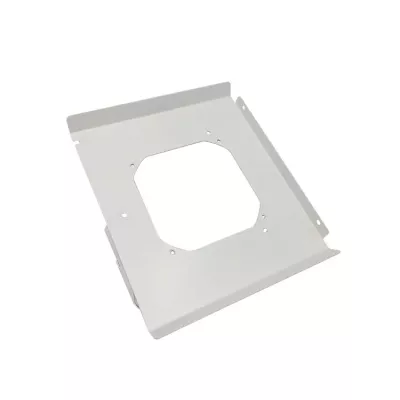
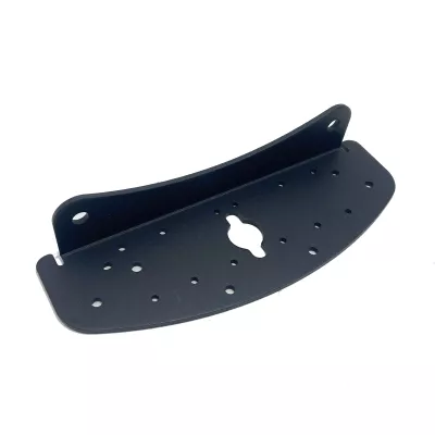
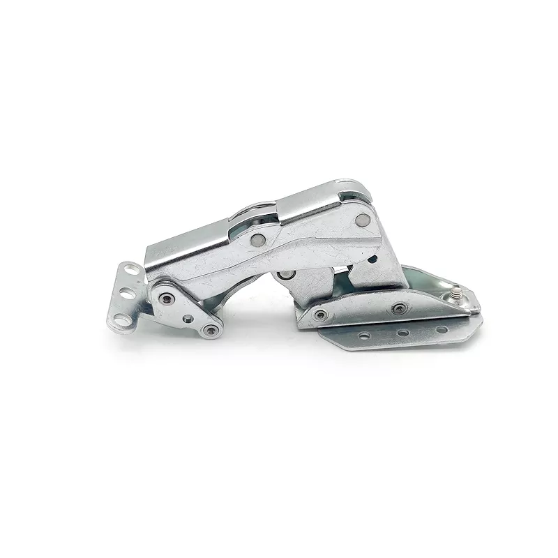
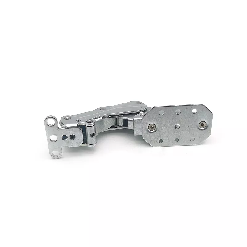
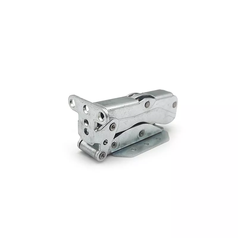
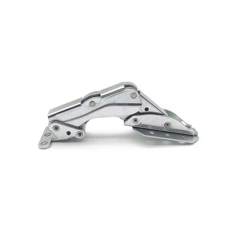
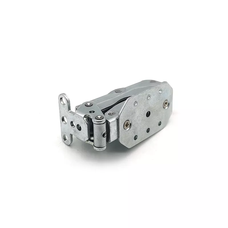
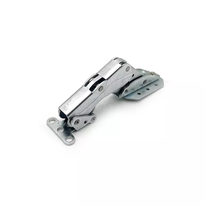
Specify the articulated plate components and the contents of any requested kit separately. The light example shows overlapping plates, pivot regions, a long central arm and fixing holes at the ends. Its linked appearance provides assembly context, without establishing a latch function, working load or cycle rating.
Locate the pivots within the assembly
Provide individual component drawings and the assembled relationship between plates, arm and end fixings. Reference hole centers, contacts and clearances to functional datums. Identify pins, bushes, fasteners or other hardware only where required, stating which items and assembly operations are included in the delivery.
- List each plate component and kit quantity.
- Define pivot centers, end fixings and mating contacts.
- Select actual metal and section requirements.
- Specify fabrication, assembly and compatible finish.
- Agree movement checks and intended-duty evidence.
Select the metal and operations by item
Steel, aluminum, copper, stainless steel and brass are separate material directions. Choose actual grade and condition for each supplied piece, including any requested stainless steel 316. Define cutting, stamping, drilling, bending and joining against the controlled design rather than assuming a single sequence applies to every part.
Accept the articulated interfaces in final condition
Mark tolerances with units and final measurement conditions at pivots and contacts. Select compatible paint, powder coating, plating or polishing where needed. Any load, operating movement, wear or automotive requirement needs actual service conditions and appropriate evidence for the defined assembly.
Include CAD, DWG, STEP, PDF or IGS geometry, quantities and material or inspection documentation. A general equipment or certificate entry does not independently establish current machinery, certification or the performance of the pictured mechanism.