Custom CNC Aluminum Milling Machining Parts | Finned Component Drawing Enquiries
-
CNC Machining or NotCnc MachiningTypeBroaching, DRILLING, Etching / Chemical Machining, Laser Machining, Milling, Other Machining Services, Turning, Wire EDM, Rapid Prototyping
-
Material CapabilitiesAluminum, Brass, Bronze, Copper, Hardened Metals, Precious Metals, Stainless Steel, Steel Alloys, PlasticMicro Machining or NotMicro Machining
-
Model NumberS2212Machining3/4/5 Axis CNC Machining/ Gantry Machining Center
-
Surface treatmentAnodized/oxide etc /powder coated/polishing/grinding/paintingTolerance±0.02 or as your drawings requirements
-
ToolingMade by ourselfApplicationIndustry/Medical/Autospare
-
MaterialAluminum / Stainless Steel / Brass /Cooper/Zinc etc...ColorSilver / Black or as per your request
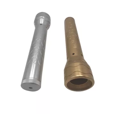
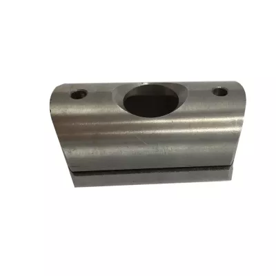
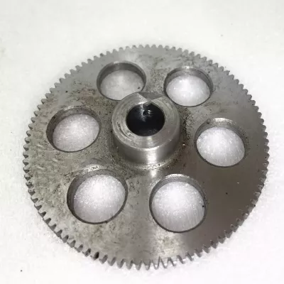
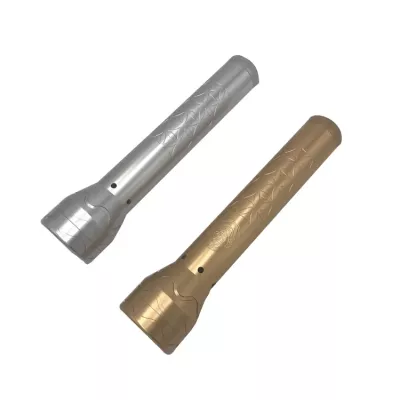
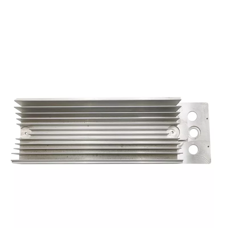
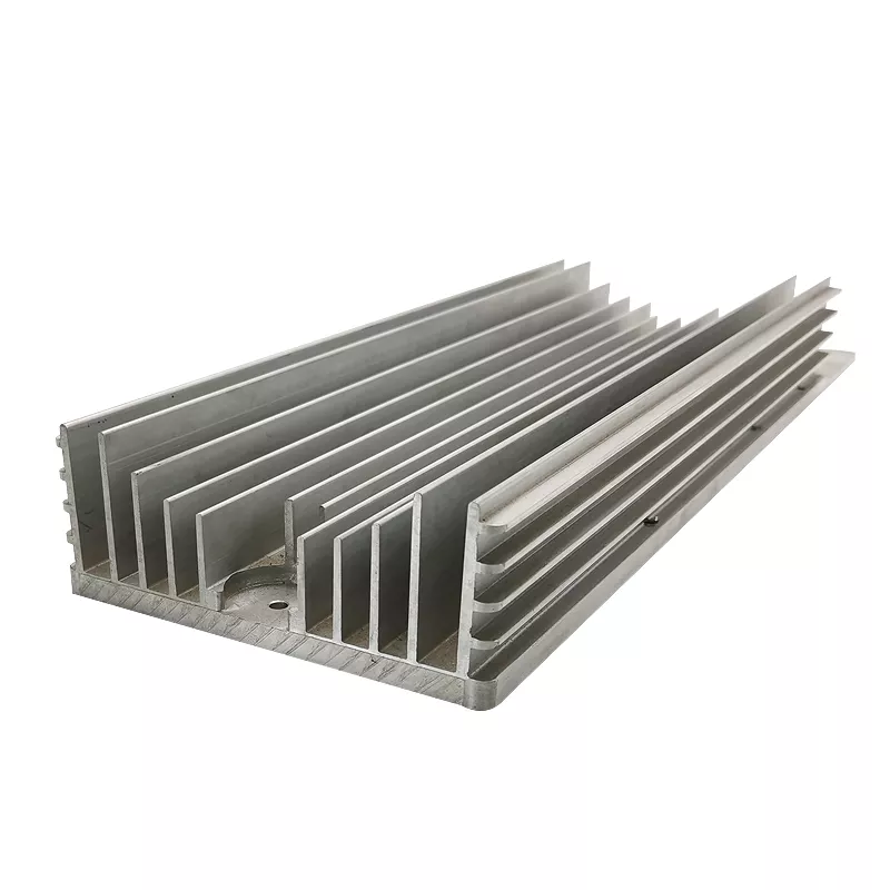
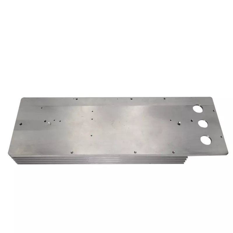
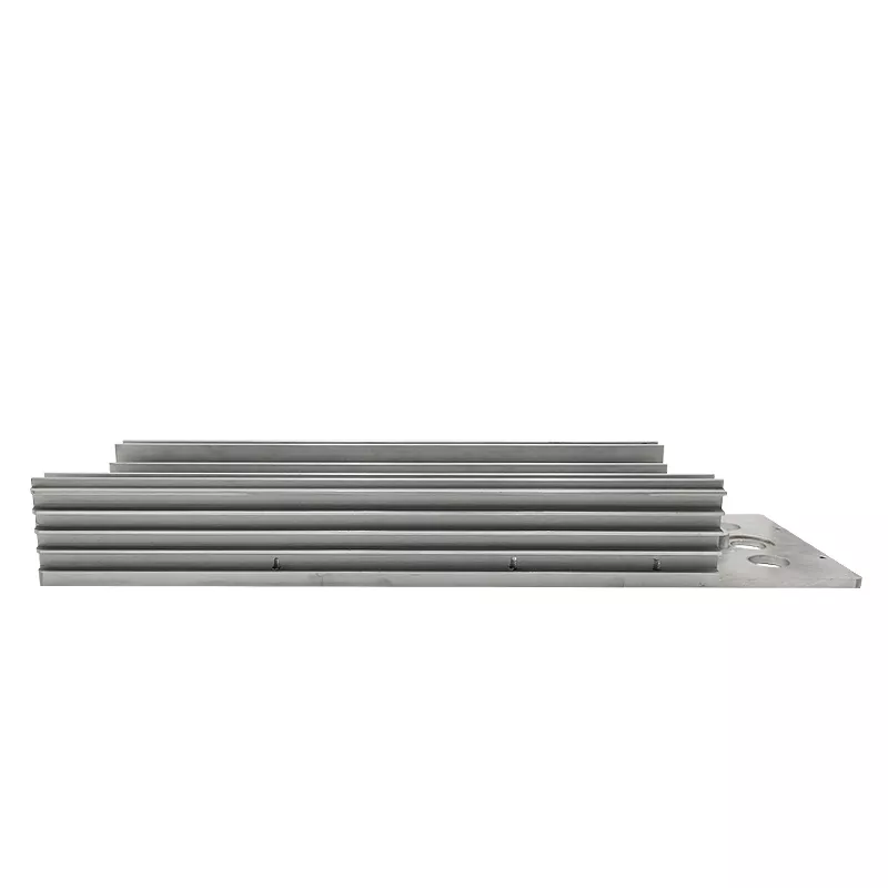
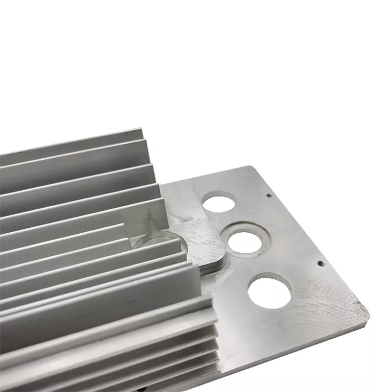
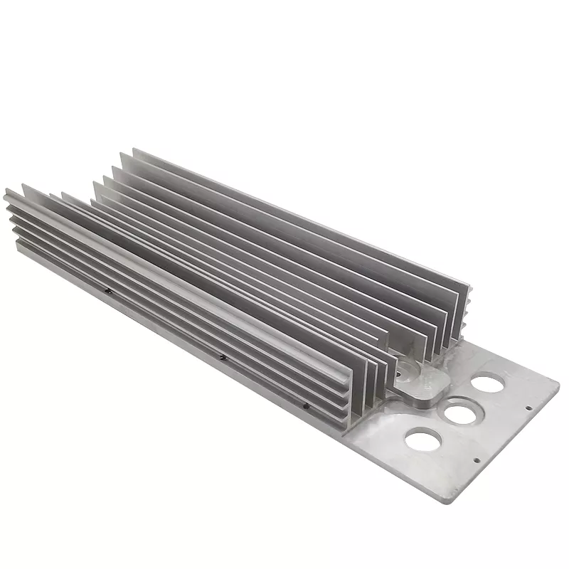
Specify the aluminum component from its actual section and mounting interfaces. The example is a long finned form with parallel plate fins, side ribs and a projecting end plate containing circular openings. It helps identify the enquiry without establishing a measured heat-dissipation result or compatibility with a particular assembly.
Define the fin field and mounting plate
Provide the section, length and the surface that contacts adjoining equipment. Locate the projecting plate and openings from the drawing references and identify clearances around the fins. Include mating parts where they determine fit, access or the contact arrangement.
Identify which surfaces require CNC milling, turning, drilling or another agreed secondary operation. A visible fin field does not independently prove the fin-making route, and the broad service menu is not a complete operation plan for every component. State the supplied condition and included parts.
Choose material, finishing and dimensional acceptance
Select the actual aluminum grade and condition required by the design. Choose anodizing, coating or another material-appropriate finish, with masking where treatment affects contact or fit. The photograph does not establish a particular alloy or coating specification.
The 3/4/5-axis and gantry references describe machining options to assess for the selected geometry. Likewise, the ±0.02 or drawing-requirements field needs units, affected dimensions and measurement criteria before it can govern inspection. Do not treat it as the same precision limit for every fin, opening and mounting surface.
Connect the component to its intended service
- Provide the controlled section and mounting-plate drawing.
- Select actual alloy, finish and final supplied condition.
- Locate holes, contact faces and CNC-finished interfaces.
- State quantities and any included assembly components.
- Define inspection and application-specific acceptance records.
If thermal performance is required, provide the heat load, ambient conditions, airflow and contact arrangement for assessment. General industrial, medical and auto-spare labels do not establish approval for those applications. Confirm the actual operating context and any evidence needed for acceptance. A clear enquiry links one finned component to a coherent material, machining and inspection scope, without assigning a functional rating from its appearance.