-
Grade6000 SeriesTemperT3-T8
-
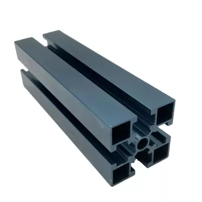
ApplicationTransportation Tools, Industrial EquipmentShapeT - Profile
-
Alloy Or NotIs AlloyModel NumberDM2012
-
Tolerance±1%Processing ServiceBending, Decoiling, Welding, Punching, Cutting, extruding
-
Delivery Time22-30 daysProduct material6061 6063 Aluminum
-
ColorBlack MetalSizeCustomized
-
Surface treatmentAnodized/oxide etc /powder coatedToolingMade by ourself
-
PackingCartonProcessSand casting +CNC Machining
-
CertificationISO9001-2008MachiningAvailable
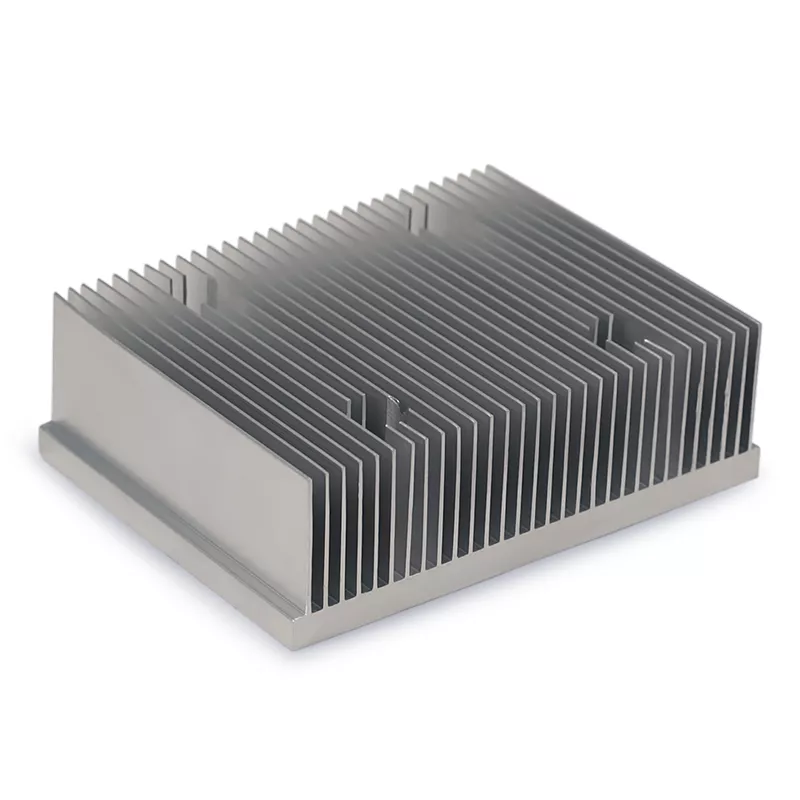
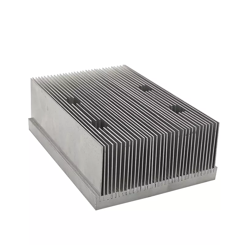
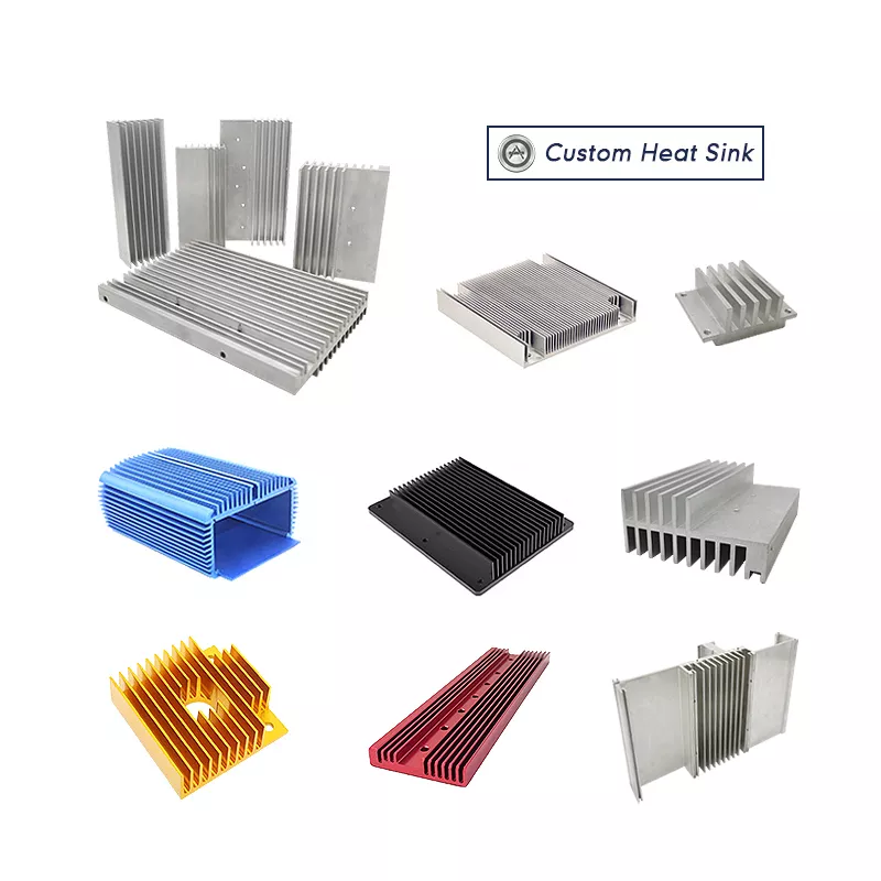
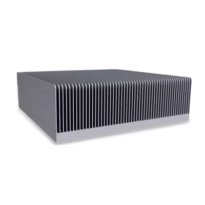
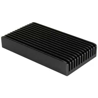
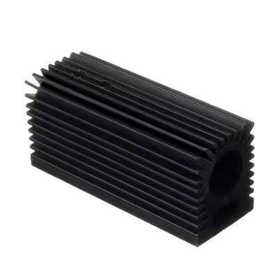
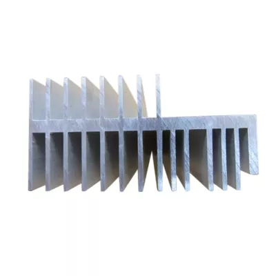
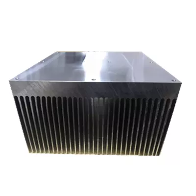
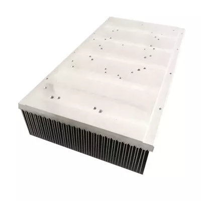
Describe the finned profile required by the actual installation. The example has a rectangular base with many thin parallel fins and locally interrupted or stepped regions in the fin field. These details are useful drawing references, while the actual material, dimensions and supplied condition must be specified for the order.
Define the base and local fin clearances
Provide the section, length and contact-face requirements, locating the interrupted regions from the assembly datums. Identify which areas provide clearance or meet adjoining parts. Mark mounting features and any machining required by the selected drawing rather than inferring a manufacturing method from the shape of the fins.
- Select the aluminum grade and temper for this relieved fin section.
- Provide the controlled base and fin-field drawing.
- Locate reliefs, contact faces and mounting interfaces.
- Define secondary work, finish and masking requirements.
- State final-condition inspection and supplied scope.
Agree dimensions and finishing for the selected part
The broad T3-T8 and ±1% fields are reference information rather than a complete material and tolerance specification. Assign limits to the features that control fit, with units and measurement criteria. Agree the profile and secondary-operation route instead of automatically adopting a historical general casting sequence.
Choose anodizing or another finish for the actual material and application. Identify surfaces where treatment affects assembly or thermal contact and state the condition in which inspection takes place. The image does not establish an actual alloy, temper or verified fin-making process.
Connect the profile to its operating context
Provide heat load, ambient conditions, airflow and the way the heat source meets the component. Transportation-tool and industrial-equipment labels do not establish model fit or a measured thermal result. If a particular application requires additional evidence, define the actual conditions and acceptance criteria. Confirm quantities and the complete delivered scope for the drawing. A clear enquiry links one fin geometry and material choice to a consistent machining, finishing and inspection plan, rather than treating a broad reference range as the specification of every illustrated part.