Custom Made Extruded 6063 Aluminum Heatsink Parts | Double-Sided Fin Enquiries
-
Grade6000 SeriesTemperT3-T8
-
ApplicationHeat Sink, Power SupplyShapeSquare
-
Alloy Or NotIs AlloyModel NumberCustomized
-
Tolerance0.05mm, ±0.05Processing ServiceBending, Decoiling, Welding, Punching, Cutting, extruding
-
Delivery Time15 daysMachiningAvailable
-
Surface treatmentAnodized/oxide etc /powder coatedToolingMade by ourself
-
Heatsink MaterialAluminumColorSilver White
-
Product nameAluminum HeatsinkMaterial6063 Aluminum Alloy
-
UsageAluminum Extruded Profiles Extrusion Aluminum
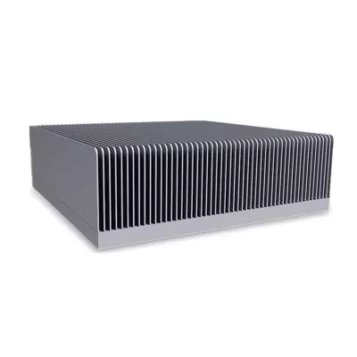
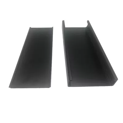
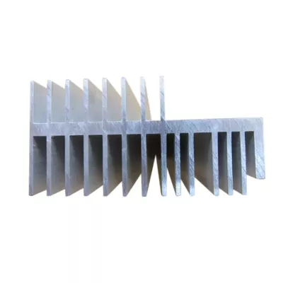
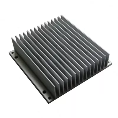
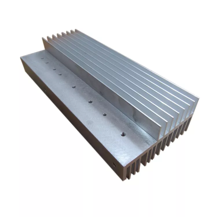
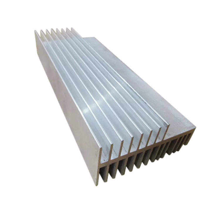
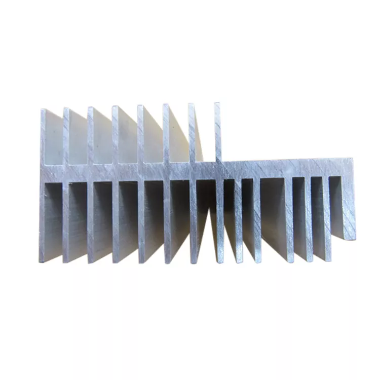
A custom extruded 6063 aluminum heatsink should be specified by its section and installation conditions. The example has a central web with parallel plate fins on opposite faces. The two fin arrangements differ, so identify which side faces the heat source and how each side fits within the assembly.
Locate the contact and mounting references
Supply the profile drawing, overall length and required quantities. Identify the surface through which heat enters the component and show the mounting arrangement. Dimension the central web, fin height and spacing where they control fit or access. The photograph does not establish one fixed section or a measured cooling capacity.
Include nearby parts where they limit clearance around either fin array. State whether the design is intended to work with a specified airflow arrangement or another defined installation condition. Heat load, ambient conditions and thermal contact requirements are inputs for assessment rather than properties that can be assumed from the appearance of the fins.
- Select the actual 6063 alloy condition required for the order.
- Provide the section, cut length and assembly envelope.
- Mark mounting holes and any secondary machining.
- Assign dimensional limits to the features that control fit.
- Define finish, contact-face treatment and inspection condition.
Specify the material and finished dimensions
The original tolerance fields include 0.05mm and a separate ±0.05 reference. Identify the affected dimensions, units and measurement criteria before using either as an acceptance requirement. They do not establish the same tolerance for every fin, cut length and machined surface. Broad temper ranges also require one selected condition for the actual order.
Connect the component to its thermal duty
State the required heat-sink or power-supply application, the contact arrangement and the criteria by which the installed component will be assessed. Choose anodizing, another finish or any masking for the design rather than automatically applying all listed treatments. Confirm the machining scope, current quantities and delivery arrangements. The historical delivery reference and general processing menu do not define the finished component or a guaranteed cooling result.