-
Grade6000 SeriesTemperT3-T8
-
ApplicationHeat Sink, Industrial EquipmentShapeT - Profile
-
Alloy Or NotIs AlloyModel NumberDmetal-200048
-
Tolerance±1%Processing ServiceCutting
-
Delivery Time22-30 daysProduct material6063 Aluminum
-
ColorBlack MetalSizeCustomized
-
Surface treatmentAnodized/oxide etc /powder coatedToolingMade by ourself
-
PackingCartonProcessSand casting +CNC Machining
-
CertificationISO9001-2008MachiningAvailable
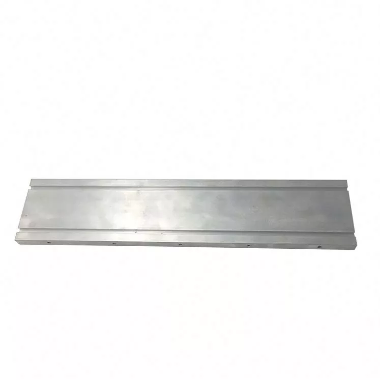
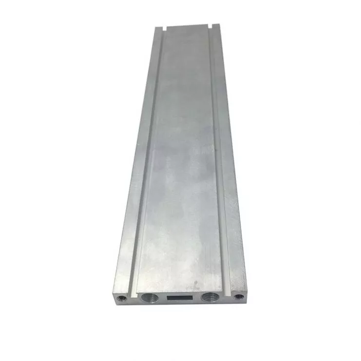
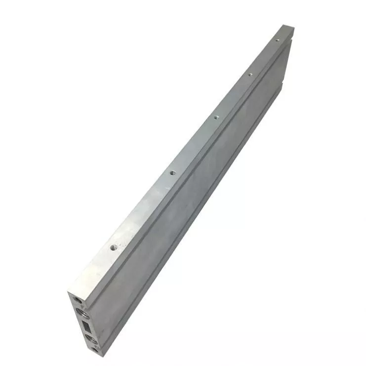
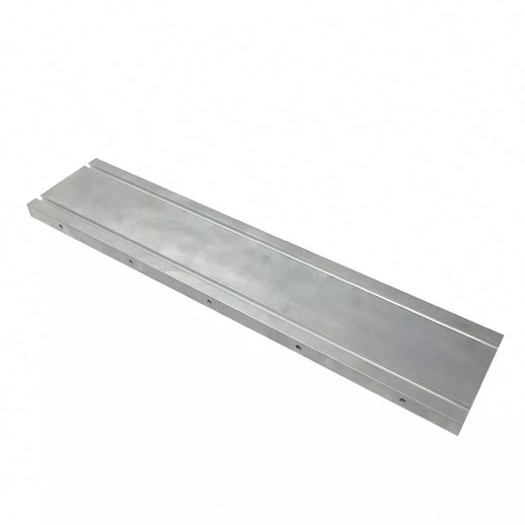
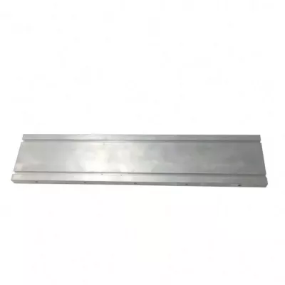
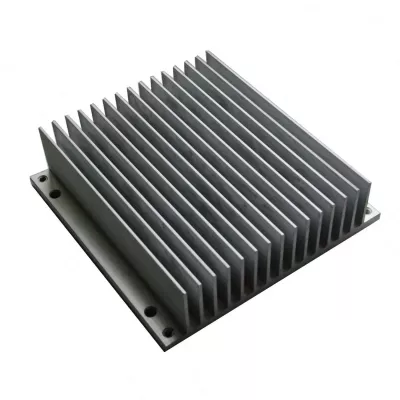
A custom aluminum cooling plate should be defined by its contact and mounting requirements. The example is a long flat section with longitudinal edge details and small circular holes. These features help identify the enquiry, but the actual section, alloy condition and cooling design must be specified for the order.
Dimension the contact plate and edge details
Supply the overall length, width and thickness, with the references used to locate fixing holes and adjoining edges. Mark the face that contacts the heat source and identify any requirements for flatness, finish or machining. Include the mating assembly where it determines clearance or the way the plate is secured.
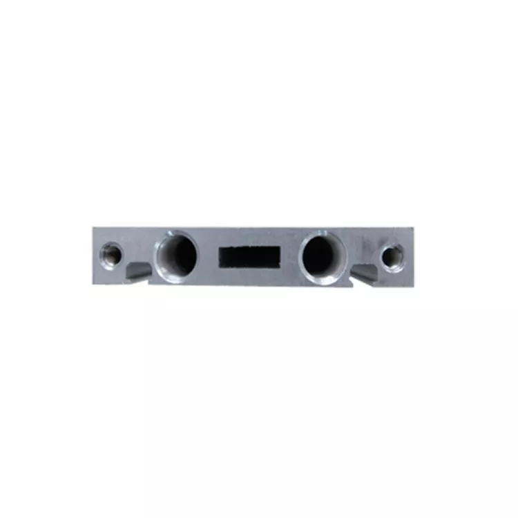
If a particular profile section is required, provide that cross-section rather than relying on a generic T-profile field. Locate grooves, lips or edge engagement features from the relevant datums. The photograph does not establish an internal passage arrangement or a fixed set of component dimensions.
- Identify the plate section and controlled drawing revision.
- Select the material condition, including 6063-T5 if required.
- Define contact faces, mounting holes and edge interfaces.
- State the solid-profile or separately specified fluid-feature scope.
- Set finished dimensions, treatment and inspection requirements.
Specify the actual cooling construction
The cooling-plate name does not prove that liquid channels, connections or a sealed cold-plate assembly are included. If the design requires fluid features, provide their own geometry and acceptance criteria. If it uses a solid profile, define the intended thermal contact and installation arrangement. Neither configuration should be inferred solely from the catalogue title.
Agree route and acceptance for the selected design
Specify heat load, ambient and installation conditions so that thermal suitability can be assessed. The historical sand-casting and ±1% fields are references rather than a complete process or tolerance plan. Agree the actual extrusion and secondary work, assigning limits to the features that matter. Choose any finish and masking for the selected alloy and contact requirements. Confirm current quantity and supplied scope against the same drawing. No leak rating or measured heat-removal result is established by the example.