-
CNC Machining or NotCnc MachiningTypeBroaching, DRILLING, Etching / Chemical Machining, Laser Machining, Milling, Other Machining Services, Turning, Wire EDM, Rapid Prototyping
-
Material CapabilitiesAluminum, Brass, Bronze, Copper, Hardened Metals, Precious Metals, Stainless Steel, Steel AlloysMicro Machining or NotMicro Machining
-
Model NumberDmetal-200444Surface treatmentSmooth
-
CertificationISO9001:2008MaterialAluminum Alloy
-
Surface finishAnodized/oxide etc /powder coatedSizeCustomized Size
-
Tolerance±0.1ToolingMade by ourself
-
Drawing Format2D/(PDF/CAD)3D(IGES/STEP)
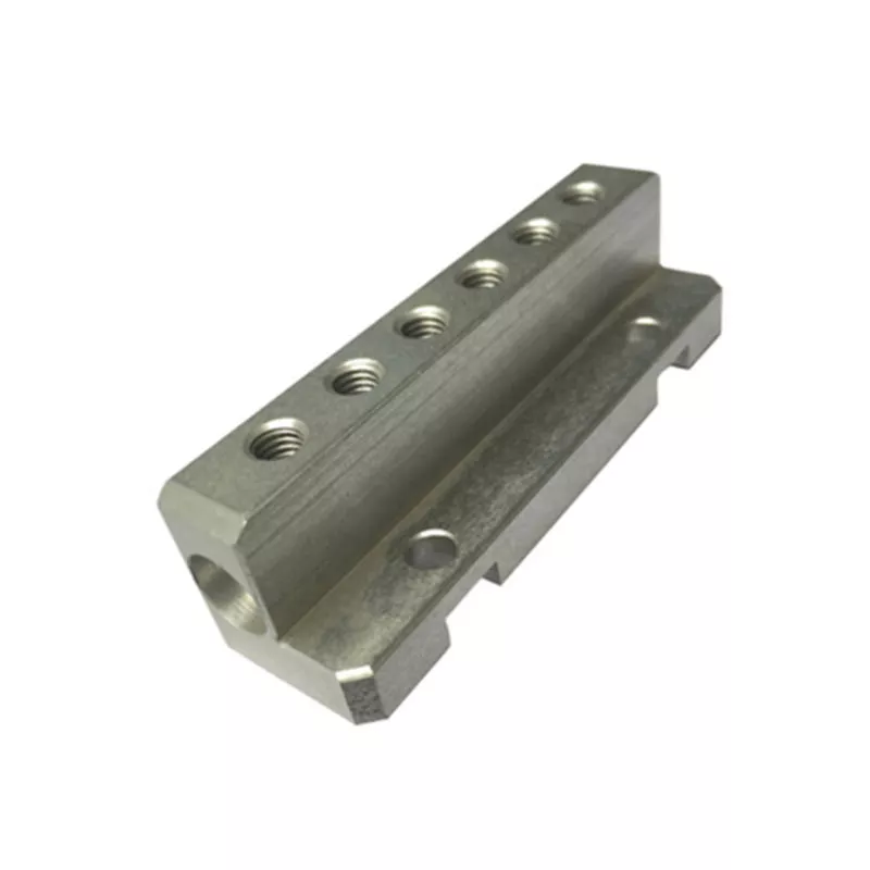
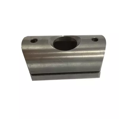
The example has a long raised rib, a row of threaded-looking openings and a stepped base with additional holes. A custom aluminum CNC milling request should define those features as a component drawing. The arrangement is not, by itself, evidence of a hydraulic manifold, pneumatic passage system or a particular equipment mounting standard.
Start with the opening pattern and internal geometry
Specify which openings are drilled and which are threaded. Give the hole diameters, depths, thread standards and positions from appropriate reference surfaces. Include the end bore and its relationship to the row of openings; an exterior image does not show whether any passages connect internally.
Use sections where needed to explain hidden connections or wall thicknesses. Describe the actual component role and mating assembly so that the requested machining scope can be reviewed against its use. Avoid assigning pressure or fluid-control performance simply because several holes are present.
Connect the raised rib to the mounting base
Dimension the rib width and height, base steps, mounting holes and contact faces. State the positional requirements that matter when the part is installed. Identify surfaces requiring machining or finish protection and make their final acceptance criteria explicit.
- Identify the component and drawing revision.
- Define the drilled and threaded opening pattern.
- Show the base interfaces and any internal passages.
- Select alloy, finish and supplied-condition inspection.
- Specify the end-bore relationship to the opening pattern.
Specify material and treatment without guessing
Aluminum alloy and anodized, oxide or powder-coated finishes are listed directions. Choose the actual grade and treatment for the order. A metallic appearance does not verify an anodized layer, its thickness or environmental performance. Mark masking requirements and any dimensions that apply after finishing.
PDF/CAD and IGES/STEP are listed drawing formats. Define units, tolerances and inspection methods for the actual features; the unitless historical tolerance is not an accepted machining commitment. Where service or qualification requirements affect selection, provide them with the drawing rather than relying on general catalogue wording.