-
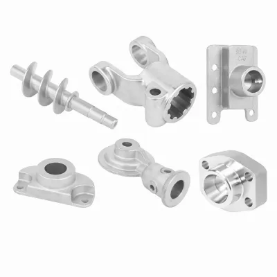
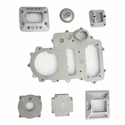
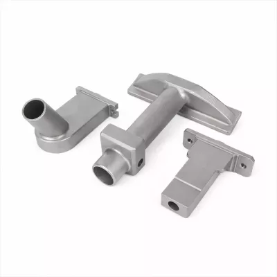
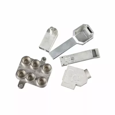
Model NumberS2211MaterialAluminum/Steel/Stainless Steel
-
ApplicationIndustryDimensionsCustomer Required
-
Surface treatmentPaint/Powder Coating/Oxidation etcMold makingBy Ourselves
-
ProcessDie Casting-deburring- MachineryServiceOEM ODM
-
FeatureEco FriendlyQuality ControlProfessional Inspection
-
PackingIndividually Packed or as per your requirements
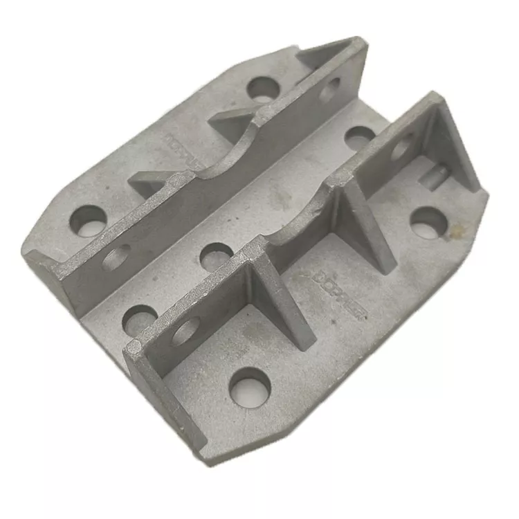
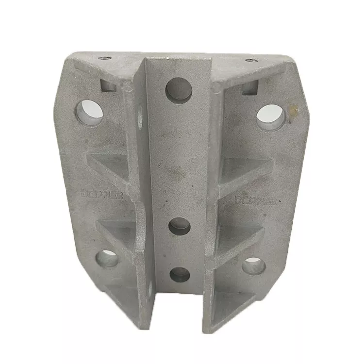
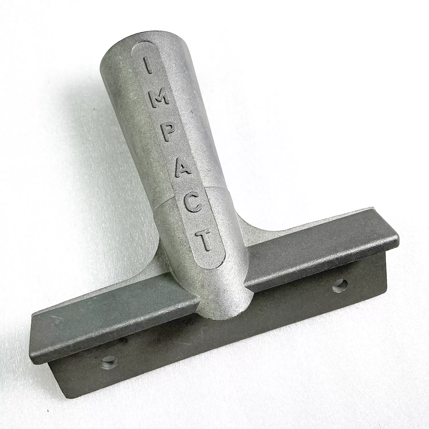
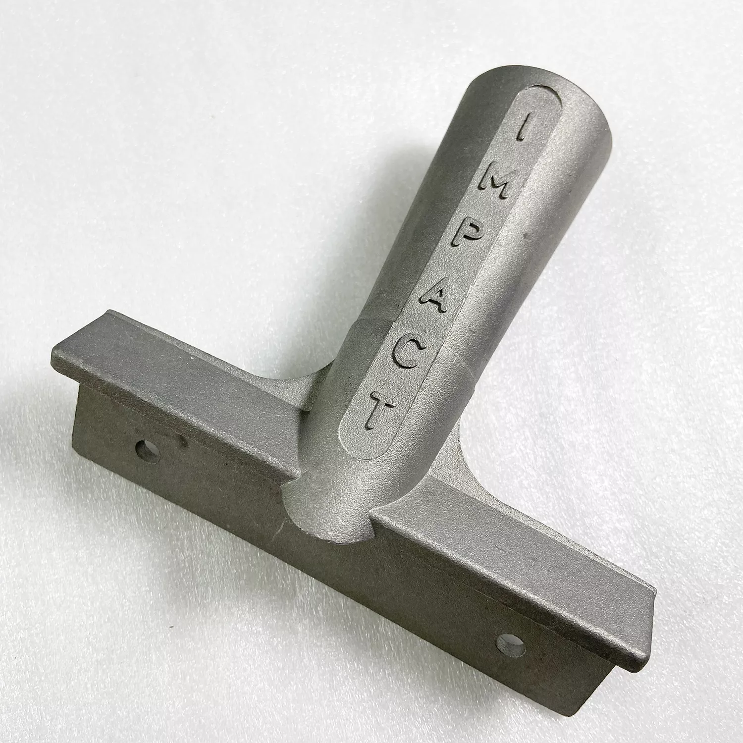
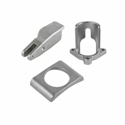
Identify the ribbed bracket component and the actual metal required by its drawing. The example has parallel raised walls, circular mounting openings, side openings and reinforcing ribs joining the walls to the base. These details do not establish an alloy, casting process or allowable installation load.
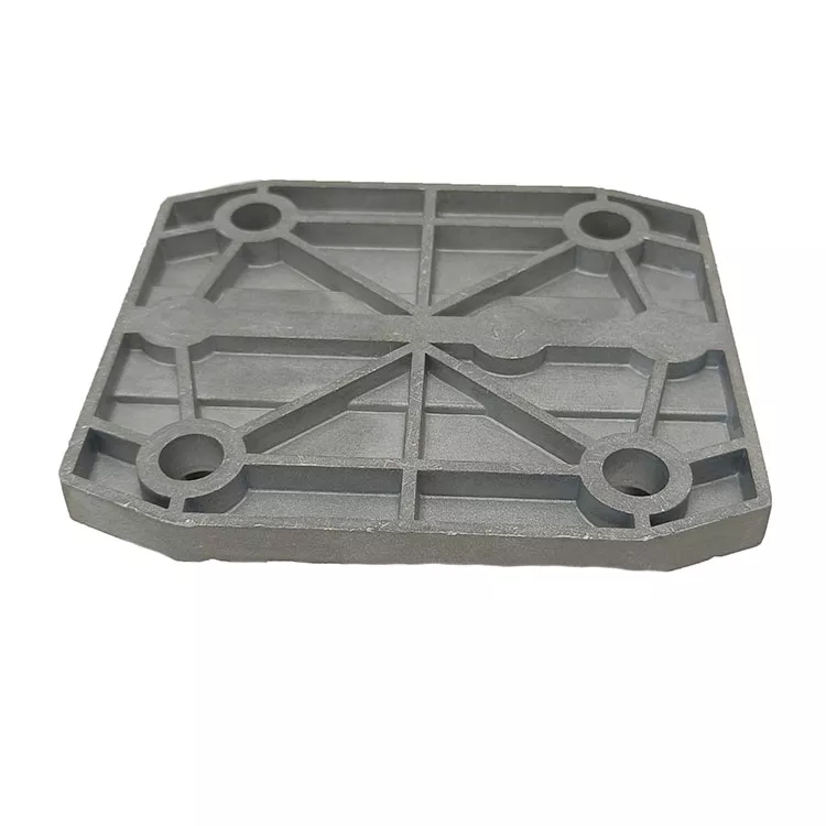
Locate walls, ribs and mounting openings
Provide the base outline, wall heights and section thicknesses, locating the openings from the assembly datums. Show the clearances and contact surfaces required by the mating components. Define the rib geometry where it affects the supplied part instead of treating an exterior photograph as a complete structural design.
- Provide the bracket drawing and mating-part references.
- Select the actual casting metal and grade.
- Dimension base, walls, ribs and opening relationships.
- Mark secondary machining and final finishing requirements.
- State quantities and dimensional or duty acceptance evidence.
Choose material and manufacturing route together
Aluminum die casting and cast-iron wording are distinct enquiry directions. Steel and stainless steel also appear as general material options. Resolve the actual component requirement into one selected grade and a suitable agreed route rather than assuming that every metal uses the same die-casting sequence.
Identify the surfaces supplied as cast and the openings or faces needing machining. Set units, tolerances and inspection criteria for the interfaces that control assembly. The example does not independently verify its material composition or prove that it was produced by a particular process.
Agree the finished bracket and operating criteria
Select a material-appropriate treatment and define the final appearance and dimensional condition. Paint, coating and oxidation terms are options to specify, not automatic proof of the treatment applied to the pictured component. Mark areas needing masking or fit protection during finishing.
If the bracket has a load-bearing or retaining duty, provide the actual installation, loading and acceptance requirements. Ribs and wall thickness seen in an image do not establish a tested structural rating. Confirm whether mating hardware or other parts are included, with quantities and documentation. A comparable enquiry links one bracket geometry to its selected material, route and final inspection records.