Custom Industrial CNC Aluminum Extrusion Profiles | Multi-Chamber Section Enquiries
-
Grade6000 SeriesTemperT3-T8
-
ApplicationHeat SinkShapeAngle
-
Alloy Or NotIs AlloyModel NumberS2301
-
Tolerance0.02mm, ±0.02Processing ServiceBending, Decoiling, Welding, Punching, Cutting, Machining
-
Delivery Time15 daysMaterial6063/ 6061 etc
-
MachiningAvailableSurface treatmentAnodized/oxide etc /powder coated
-
ToolingMade by ourselfSurface ColorCustomized Panton Colors
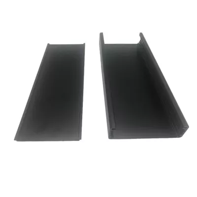
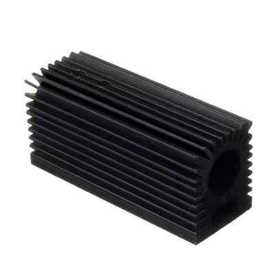
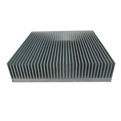
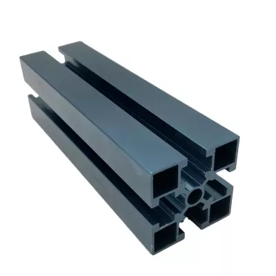
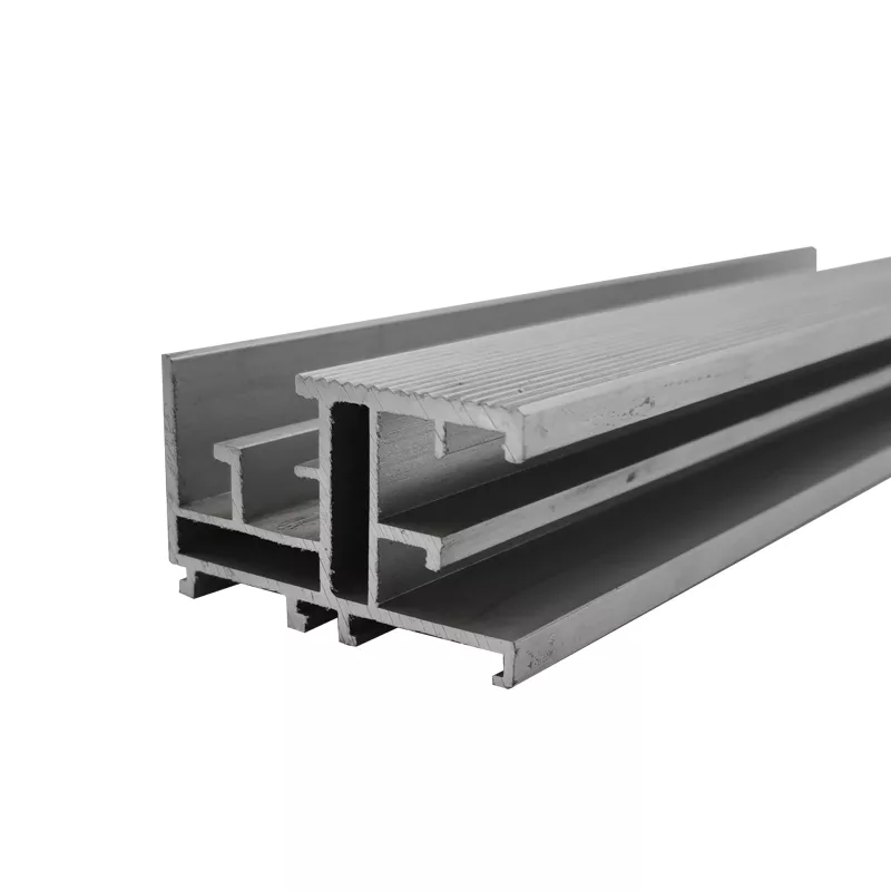
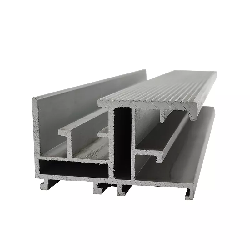
Specify the multi-chamber aluminum section and the interfaces it must provide. The example has a broad grooved upper face, internal rectangular cavities and open longitudinal channels or projecting lips. These details help identify the enquiry without establishing a particular floor, window or other complete installation.
Draw the cavities and engaging edges
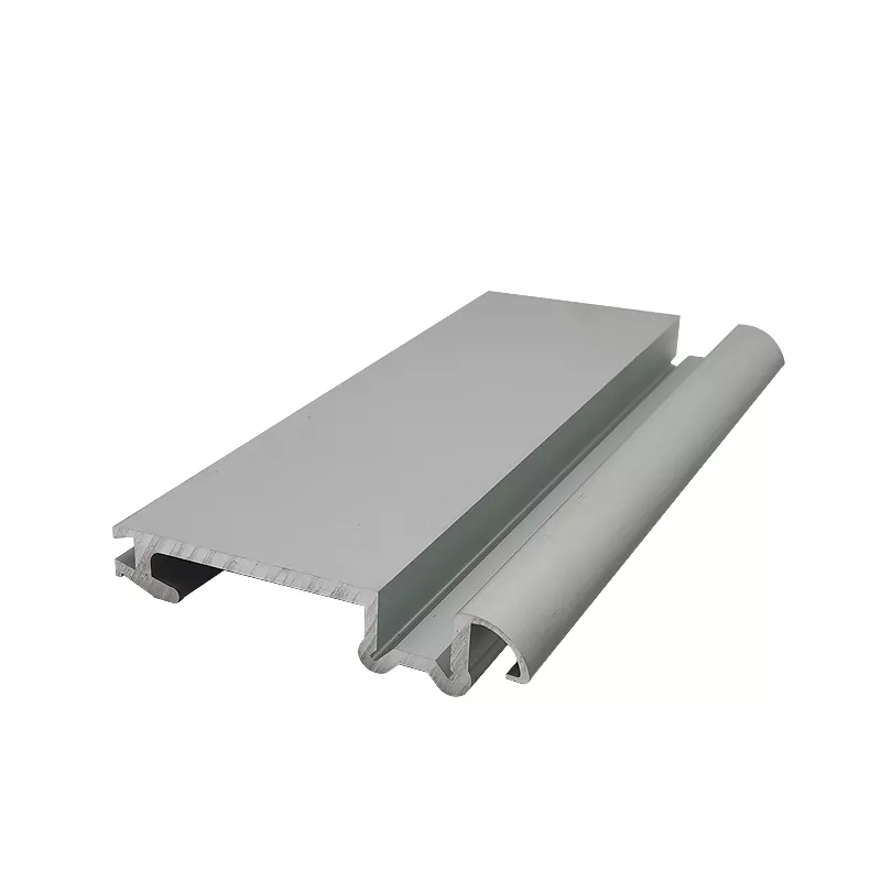
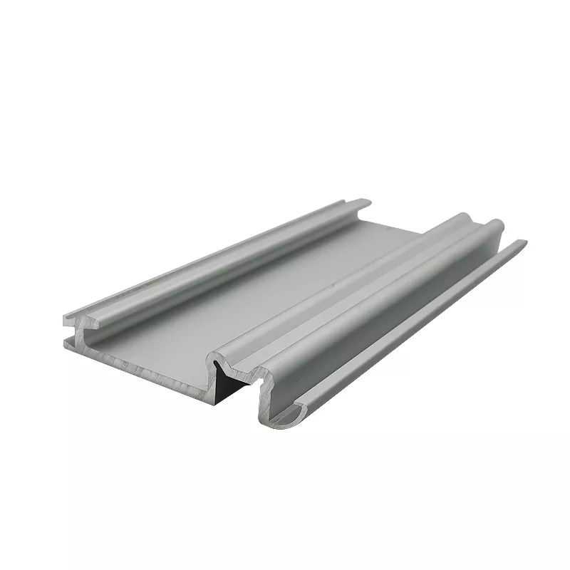
Provide the actual cross-section, wall geometry and cut length. Locate lips, channels and contact surfaces from the assembly references. Include adjoining parts where they determine the clearance or engagement of the section. A general angle-shape field should not replace the drawing of this multi-chamber component.
- Specify the selected aluminum alloy and temper.
- Provide the controlled section and component revision.
- Locate cavities, lips and the required mounting interfaces.
- Identify CNC-finished ends, holes or contact faces.
- Define finish and inspection in the supplied condition.
Separate extrusion geometry from CNC work
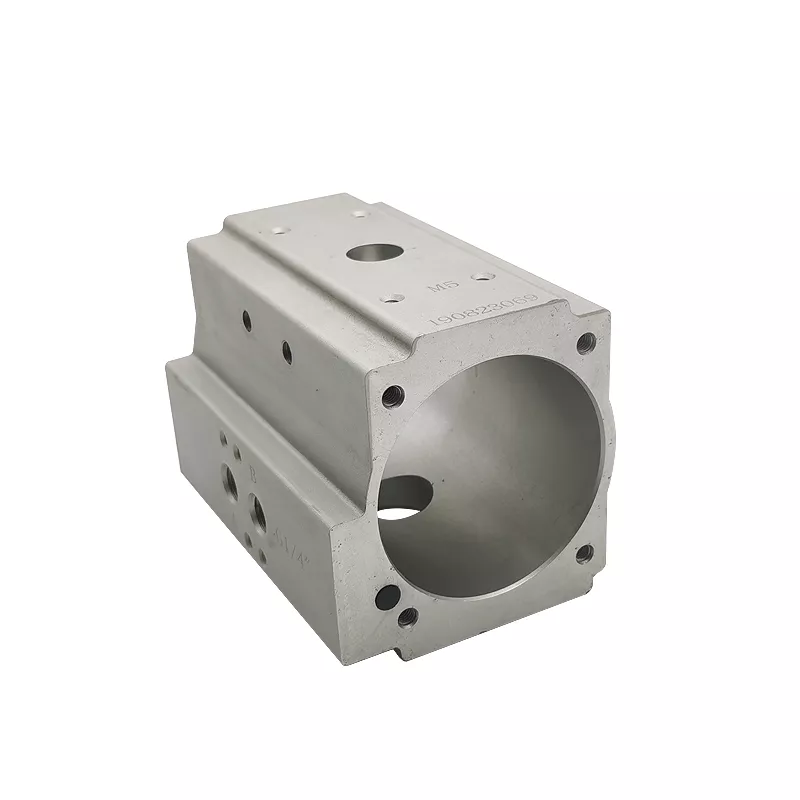
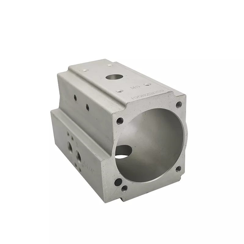
State which features are included in the profile section and which require machining after manufacture. Mark their dimensional and positional limits from the appropriate datums. The word CNC does not establish a universal setup or the same operation for every surface.
Select the actual 6061 or 6063 condition and agree the route and secondary operations for that design. The 0.02mm and ±0.02 entries are references requiring affected dimensions, units and measurement criteria; they do not define an order-wide tolerance for every wall, cavity and cut length.
Set the installation and finished acceptance
Identify the actual application and any loading, contact or environmental conditions that affect selection. The grooved surface and hollow chambers do not establish a load rating, a thermal result or approval for a particular building system. Choose finish and masking for the selected material and mating interfaces. Confirm quantities, documentation and the complete delivered scope. A comparable enquiry links one section drawing and machining plan to clear final-condition inspection requirements, rather than relying on the appearance of the profile to prove its intended function.