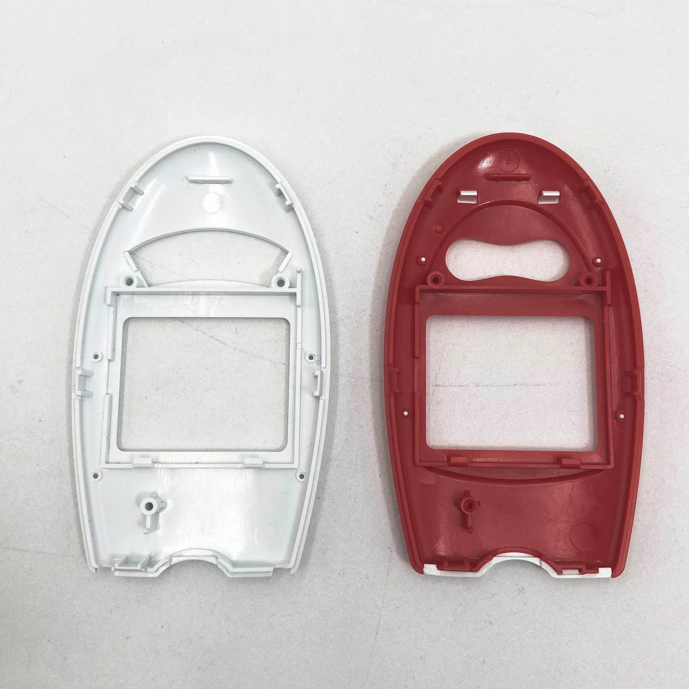
Custom Nylon ABS PP PC Injection Molded Plastic Parts | Ribbed Strips and Carriers
-
Model NumberS2104Plastic Modling TypeInjection
-
Processing ServiceMouldingColorCan be customized
-
SizeCustomized SizeMaterialPA66/PP/ABS /PC, Etc
-
CertificationROHSFeatureHigh Precision
-
ShapeCustomized ShapesPackingStandard Carton Box
-
ServicePrompt DeliverySurface finishMatt Surface
-
PackagePP Bag
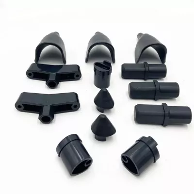
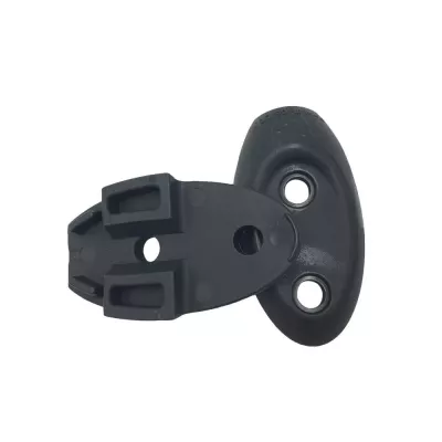
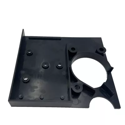
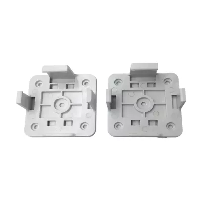
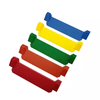
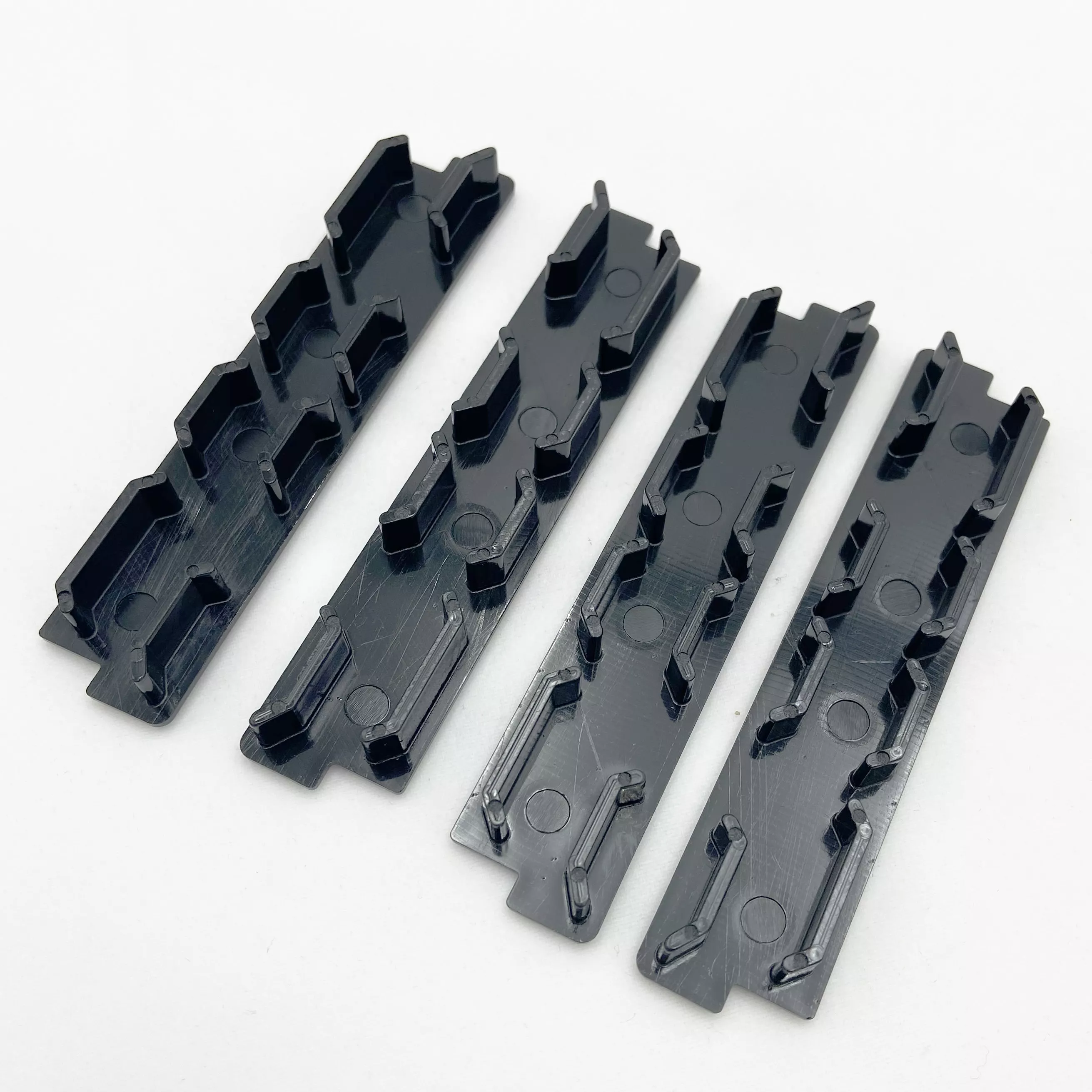
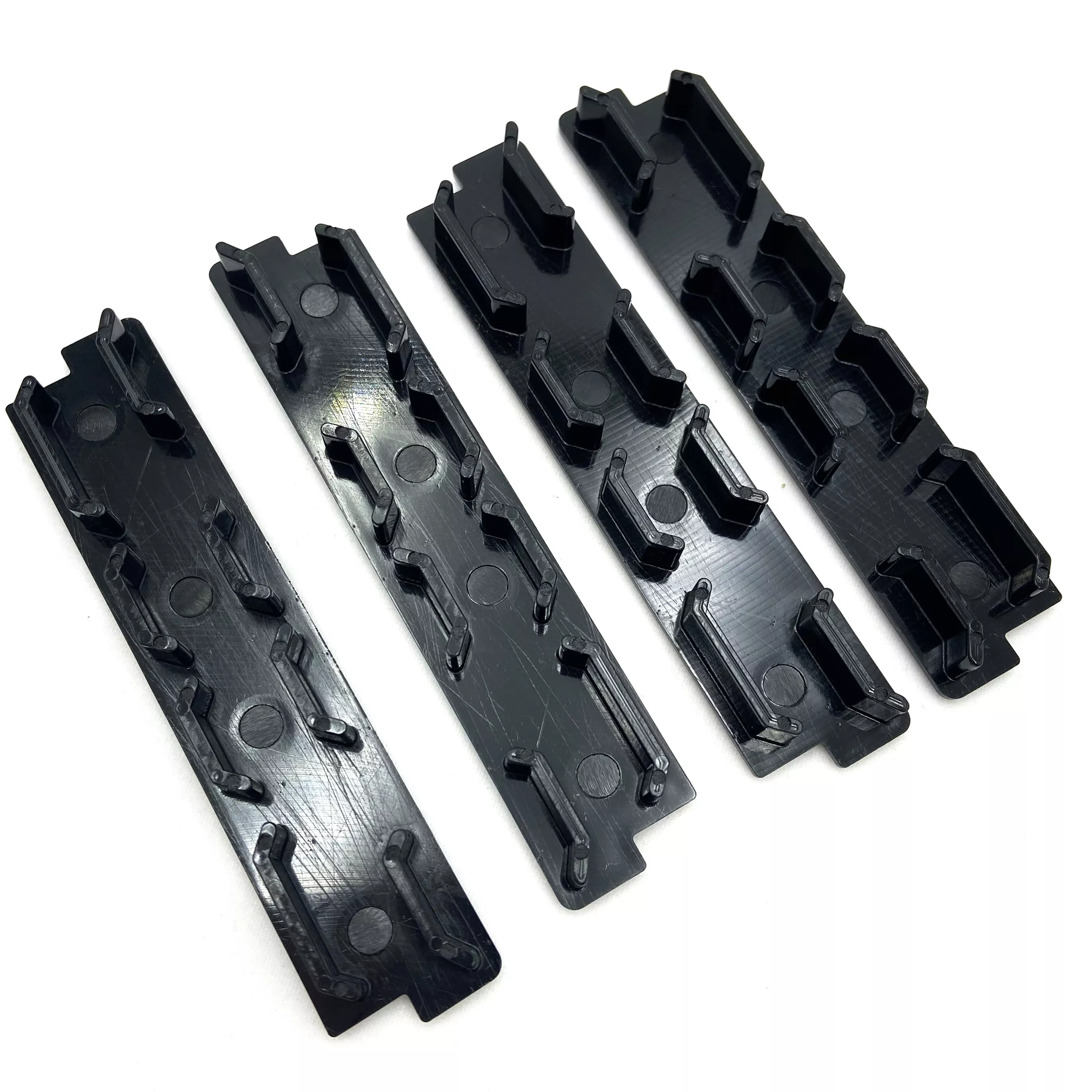
Identify each ribbed strip or carrier by its upright features and end arrangement. The four black examples show elongated bodies, repeated projections and circular recesses with differing details. The group does not establish identical dimensions, a supplied set or a shared mounting interface.
Locate upright ribs from the strip ends
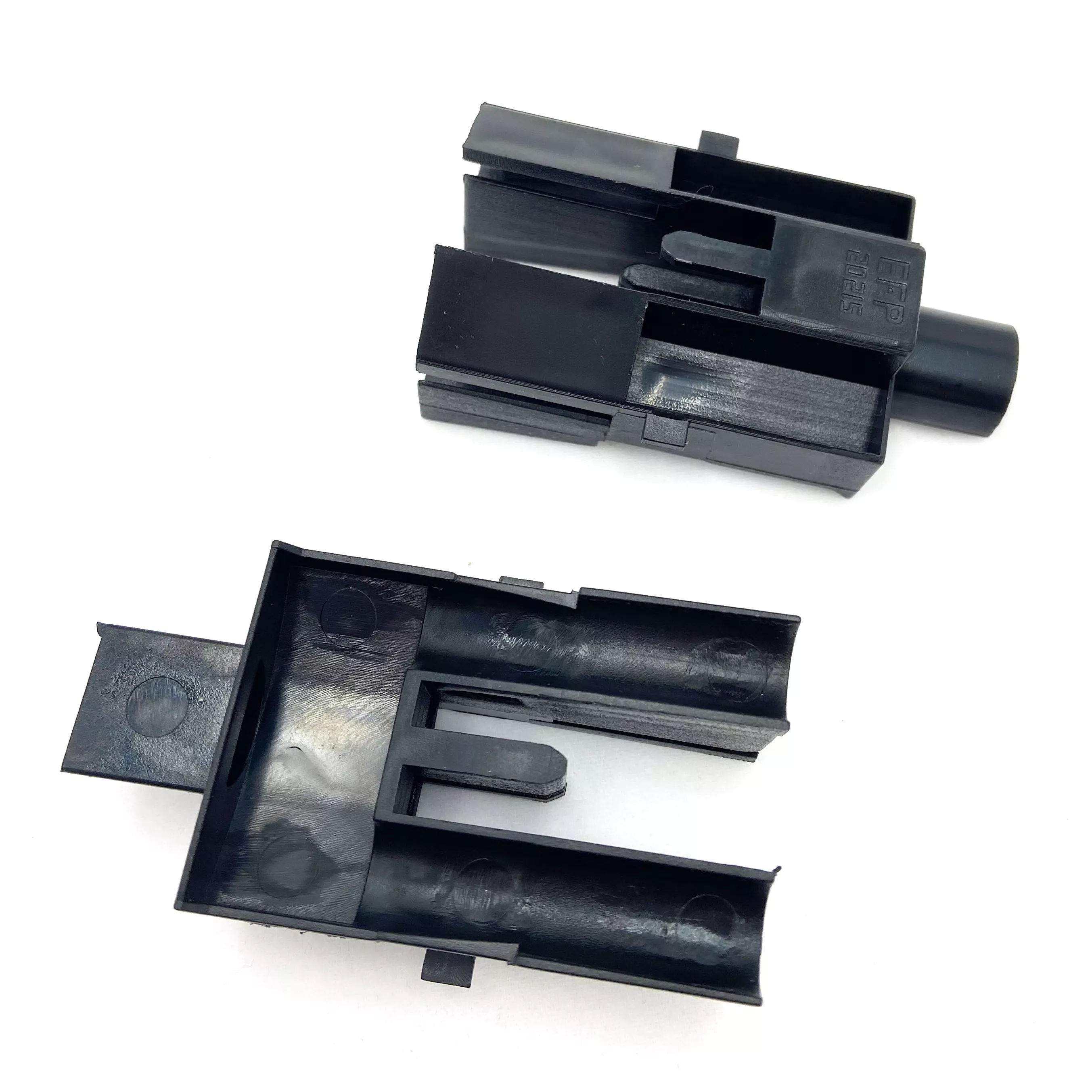
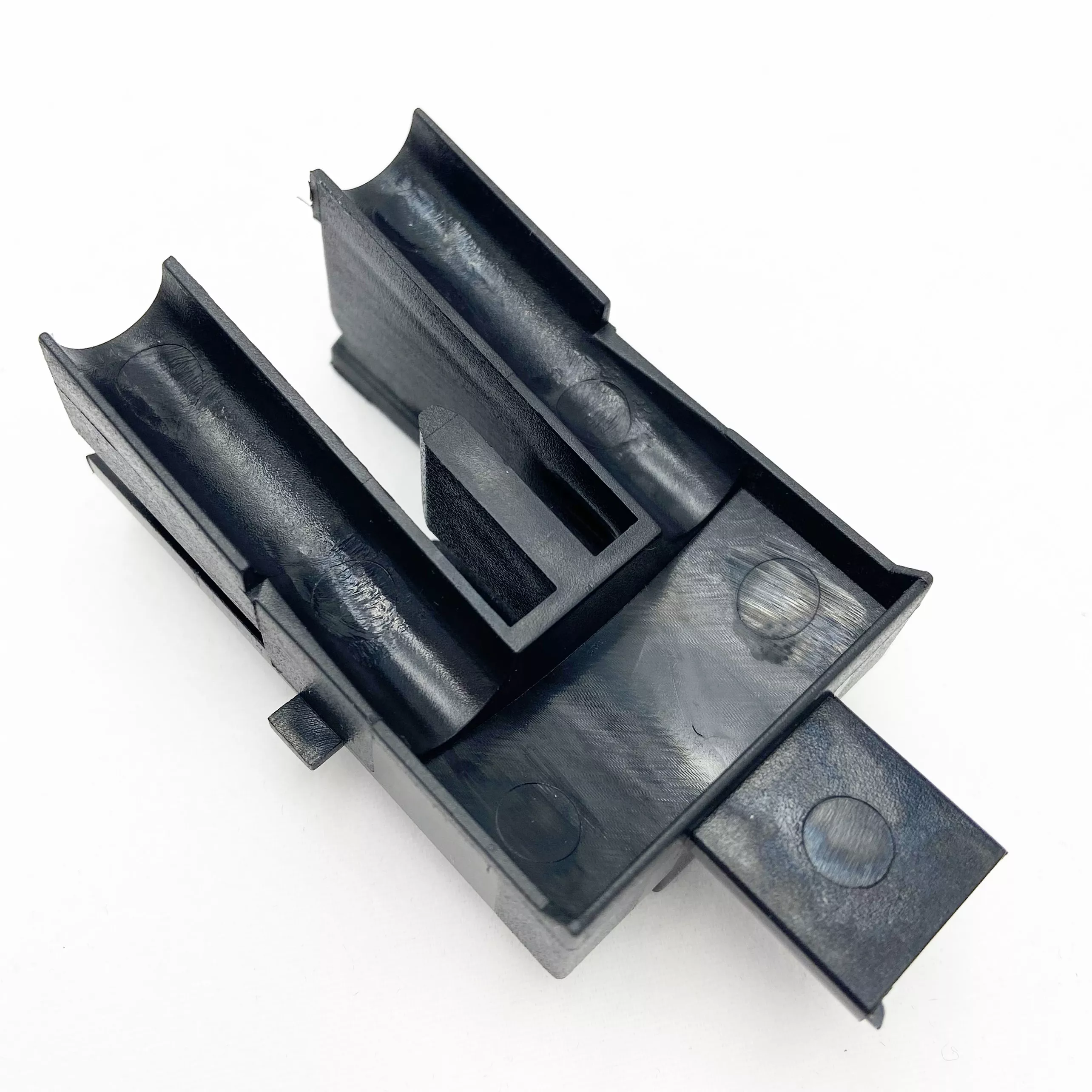
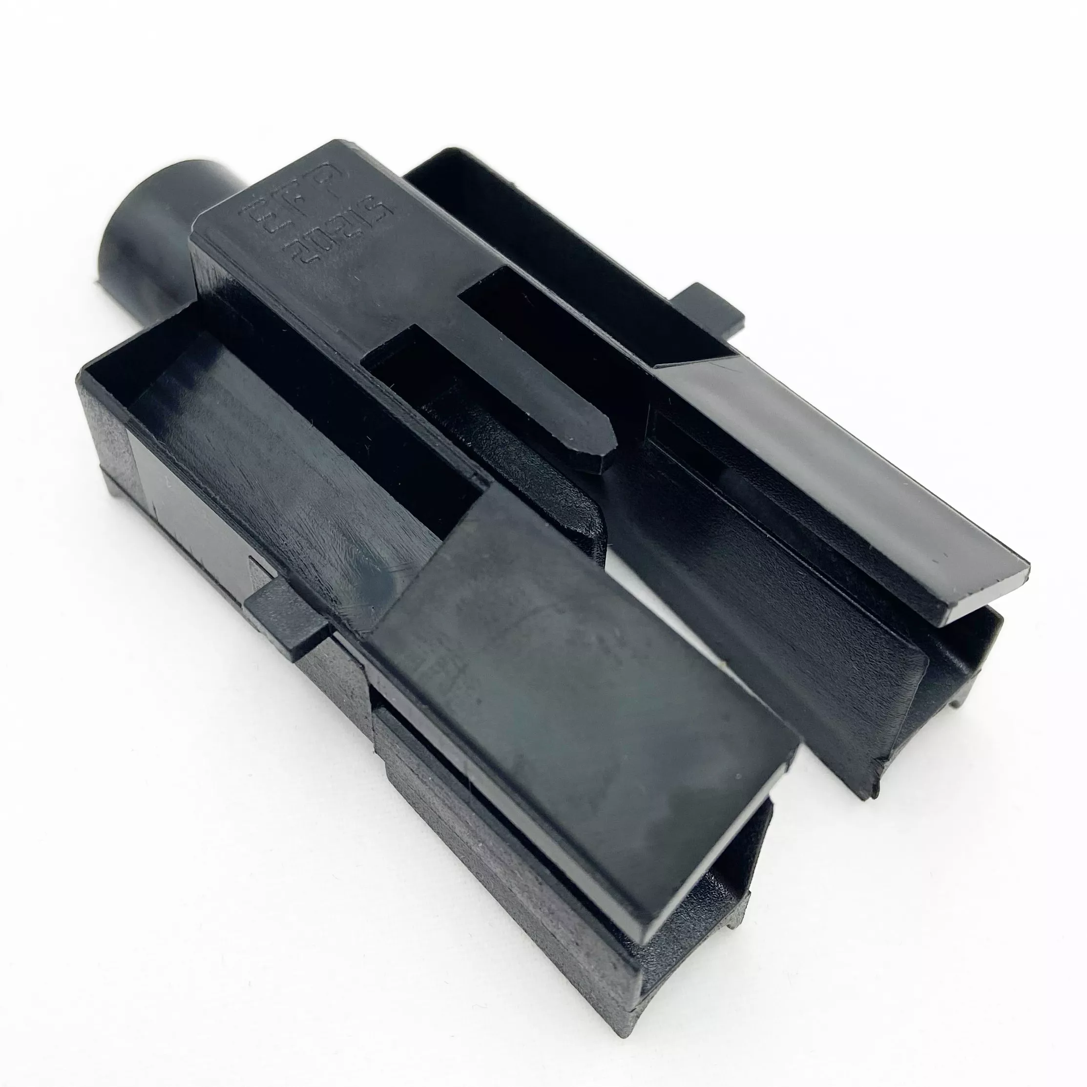
Provide the strip section, overall geometry and positions of each upright feature. Locate circular recesses and end details from controlled references rather than scaling the photograph. Identify the adjoining components and any clearance or contact relationships that determine the finished fit of the individual carrier.
- Reference each ribbed strip and drawing revision.
- Locate upright features, recesses and end details.
- Select the actual nylon, ABS, PP or PC grade.
- Define color and the required matt surface.
- Agree fit inspection and material documentation.
Choose the resin for the defined component
Nylon, ABS, PP and PC are separate material directions. Specify the actual formulation, required condition and relevant documentation, including any particular nylon grade. Define appearance using a color reference and agreed matt-surface criteria where needed; black appearance alone identifies neither material chemistry nor performance.
Inspect the molded carrier in its delivered condition
Mark dimensional tolerances and the measurement conditions at the working interfaces. If the strip has mechanical or environmental requirements, provide real operating conditions and the applicable acceptance method. Neither repeated ribs nor a generic precision description establishes a load or compliance rating.
Include quantities and controlled geometry for each required configuration. Keep separate references for differing ends or feature patterns so the proposed molding scope can be checked against the correct assembly requirement.