Custom Nylon Plastic Injection Molded Brackets | Round-Opening Mounting Components
-
Model NumberS2406Plastic Modling TypeInjection
-
Processing ServiceMoulding, Cutting, PaintingCertificationISO9001 CE
-
MaterialPA66/PP/ABS /PC, EtcFeatureHigh Precision Injection Parts
-
Product namePlastic Injection PartsDrawing Format2D/(PDF/CAD)3D(IGES/STEP)
-
Surface treatmentPolish. Etched. Texture.electroplating.paintingColorCustomer's Request
-
ProcessInjection Mould Plastic PartApplicationIndustrial Plastic Parts
-
KeywordPlastic injection
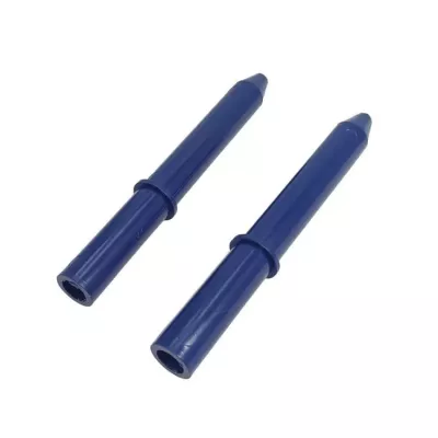
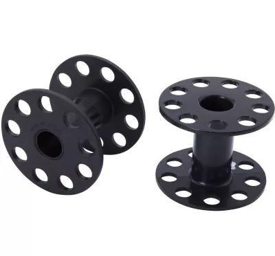
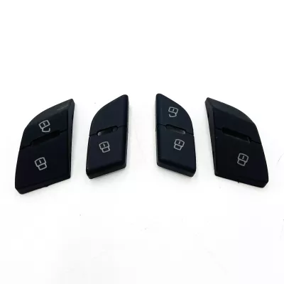
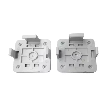
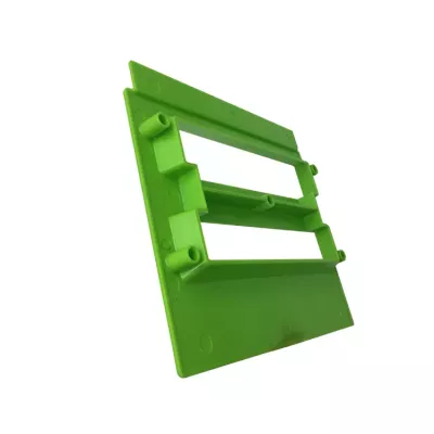
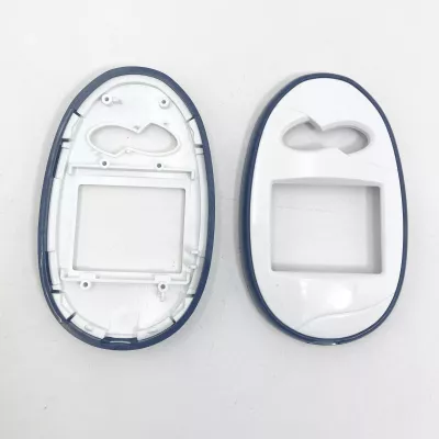
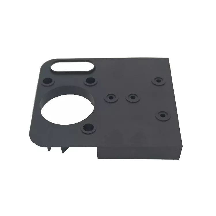
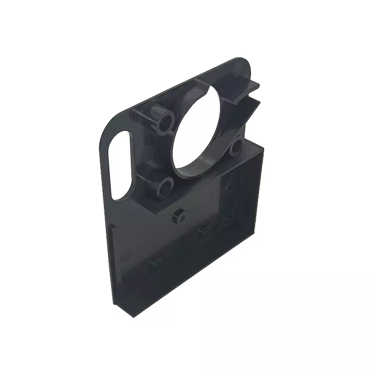
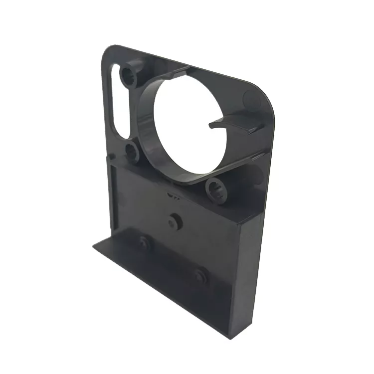
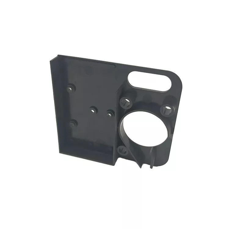
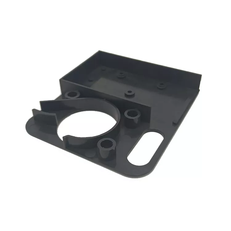
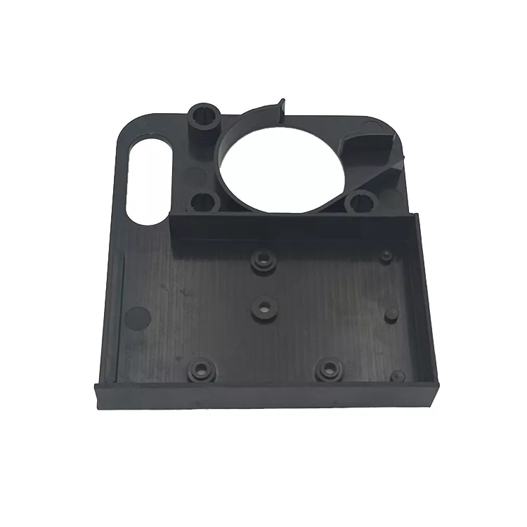
Define the mounting body through its large round opening, elongated slot and lower tray-like region. The dark example also shows raised bosses and an angular perimeter. These features identify visible geometry, but do not establish nylon grade, allowable bracket load or compatibility with a particular machine or electrical assembly.
Relate the opening and slot to the fixing bosses
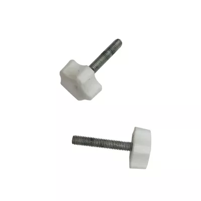
Provide sections and assembly datums for the upper opening, side slot and lower mounting region. Identify adjoining components and any contact, clearance or retention requirements. Specify inserts, threads or fasteners separately and state whether they accompany the molded body.
Define nylon and the molding process
Choose the exact nylon formulation and required condition, with relevant material documentation. Other listed polymers are separate material options. The source uses injection molding for this plastic-part direction; any alternative molding or casting request needs its own agreed process scope rather than an assumed equivalence between routes.
- Identify the round-opening mounting body and revision.
- Dimension slot, opening, bosses and tray contacts.
- Select the exact nylon grade and condition.
- Specify compatible finish and included hardware.
- Agree interface inspection and application tests.
Accept the finished mounting relationships
Mark drawing tolerances with units and final measurement conditions at the working contacts. Define actual service conditions and suitable evidence for any mechanical, environmental or electrical requirement. Shape alone does not demonstrate a working load or completed qualification.
Include PDF/CAD or IGES/STEP geometry, quantities, individual drawing revisions and requested inspection records. Keep the supplied component definition explicit when comparing proposed molding and finishing plans.