
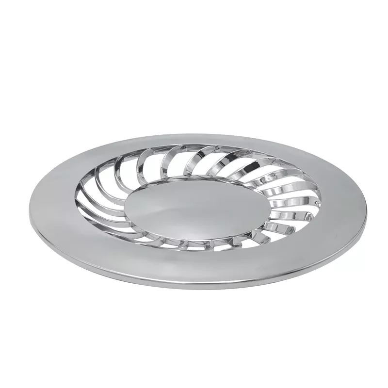
Custom Drawing Plastic Injection Moulding and Electroplate Parts | Circular Slotted Components
-
Model NumberDmetal-2007Plastic Modling TypeInjection
-
Processing ServiceMoulding, CuttingColorCustomized
-
SizeCustomized SizeMaterialPA66/PP/ABS /PC, Etc
-
CertificationROHSFeatureHigh Precision
-
ShapeCustomized ShapesPackingStandard Carton Box
-
ServicePrompt DeliverySurface finishMatt Surface
-
PackagePP Bag
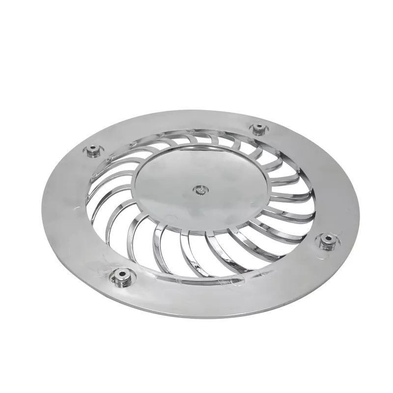
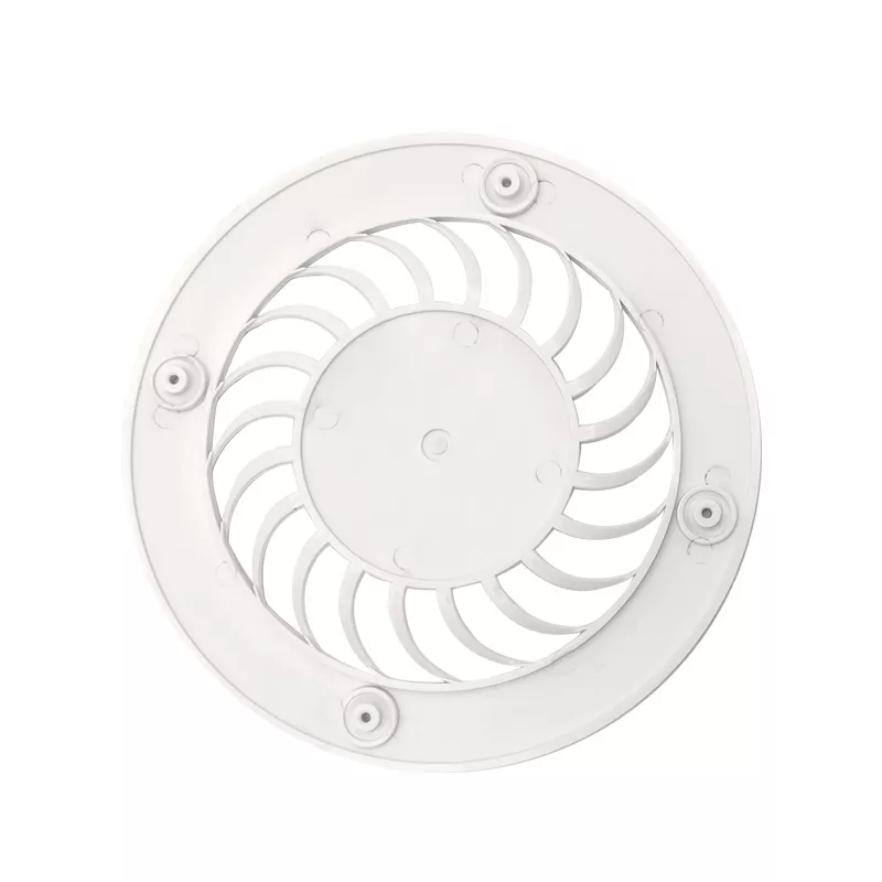
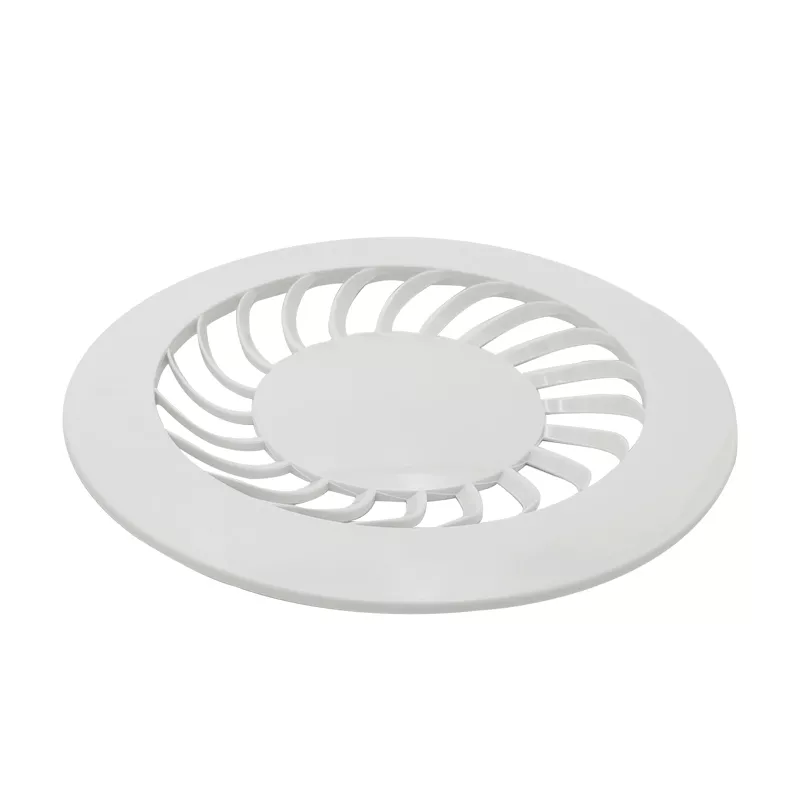
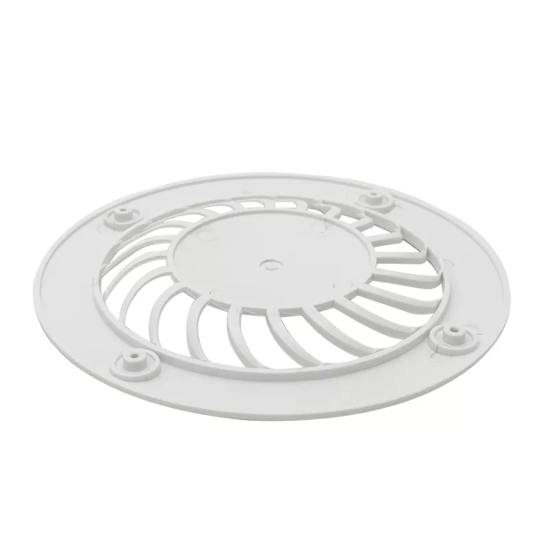
Define the circular component through its outer rim, central region and repeated curved openings. The bright example provides an appearance reference, but does not independently establish plastic composition, electroplating chemistry or a tested airflow function. Specify the actual substrate and finished construction through the order drawing.
Relate the curved openings to the rim
Provide sections showing the central region, slotted area and outer contact surfaces. Locate any fixing or retention details from assembly datums and identify adjoining components. Distinguish an open slot from a recessed feature on the drawing rather than relying on reflective highlights to define the geometry.
- Identify the circular component and drawing revision.
- Dimension rim, central region and curved openings.
- Select actual resin and required molded condition.
- Define compatible electroplate system and masking.
- Agree appearance, adhesion and dimensional checks.
Specify plating independently of molding
Choose the actual polymer grade and the proposed compatible surface system. Define required color, gloss or matt appearance, treatment boundaries and any adhesion or environmental acceptance methods. A metallic-looking image does not prove a particular plating stack or that every listed plastic supports the same treatment.
Accept the finished component for its use
Mark tolerances with units and final measurement conditions at the working interfaces. Where airflow, mechanical or environmental performance matters, provide actual operating conditions and applicable tests. Appearance alone establishes neither a flow rating nor suitability for a particular installation.
Include quantities, controlled geometry and required material or inspection records. Keep the requested coating and component scope explicit when comparing proposed molding and finishing plans.