Custom CNC Milling Aluminum Extrusion Profile Parts | Drawing-Based Machining Enquiries
-
CNC Machining or NotCnc MachiningTypeBroaching, DRILLING, Etching / Chemical Machining, Laser Machining, Milling, Other Machining Services, Rapid Prototyping, Turning, Wire EDM
-
Material CapabilitiesAluminum, Brass, Bronze, Copper, Hardened Metals, Precious Metals, Stainless Steel, Steel AlloysMicro Machining or NotMicro Machining
-
Model NumberDmetal-200448Surface treatmentSmooth
-
CertificationISO9001:2008MaterialAluminum Alloy
-
Surface finishAnodized/oxide etc /powder coatedSizeCustomized Size
-
Tolerance±0.1ToolingMade by ourself
-
Drawing Format2D/(PDF/CAD)3D(IGES/STEP)MOQ100pcs
-
Materials Avaliablealuminum/ stainsteel steel/ brass/ zinc
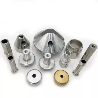
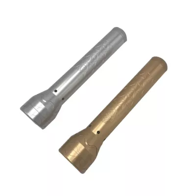
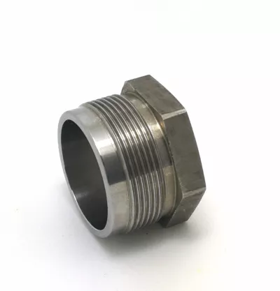
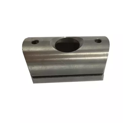
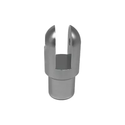
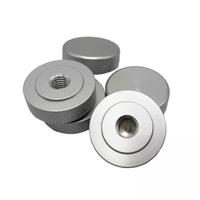
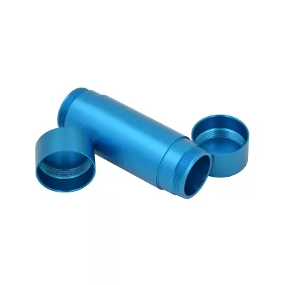
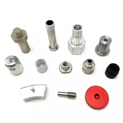
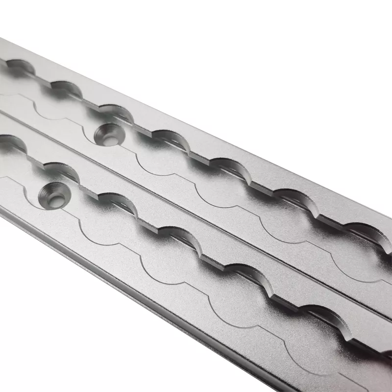
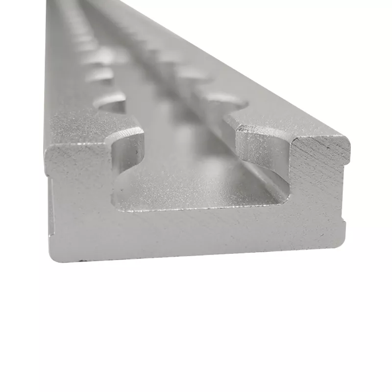
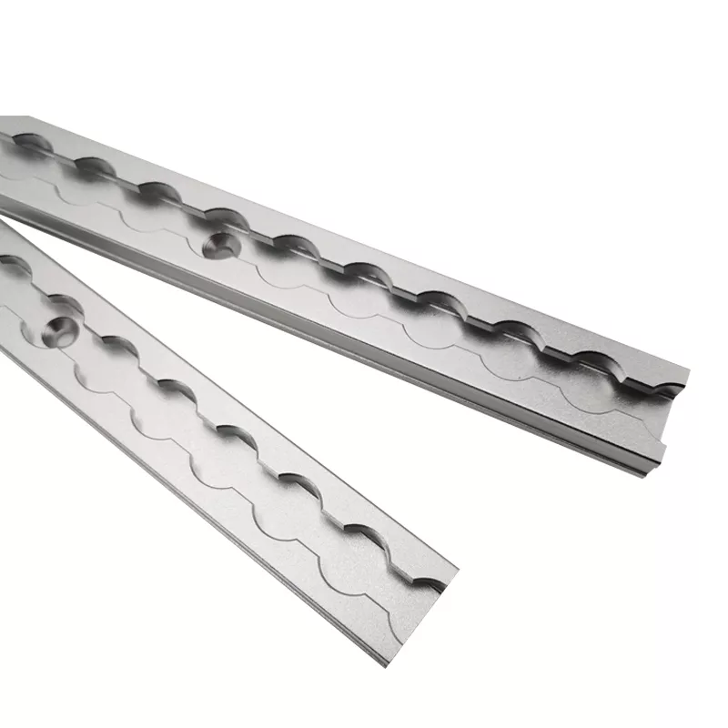
Define the aluminum profile component through its section and repeated interface geometry. The examples are long narrow parts with rounded recesses or openings along their length and straight edge regions. Their appearance does not establish the actual extrusion route, material grade or function in an assembly.
Dimension the section and repeated pattern
Provide the full cross-section, individual cut length and the geometry of each rounded feature. Locate the repeated pattern from the component datums, with the spacing and positional requirements that control assembly. Include adjoining parts where they determine engagement or clearance.
- Supply the profile section and finished drawing revision.
- Define rounded openings, recesses and repeat spacing.
- Locate the pattern from the actual assembly references.
- Select material, machining and compatible finishing.
- State final inspection and the included component scope.
Separate profile manufacture from CNC milling
The title identifies extrusion-profile machining as a sourcing direction. Specify the starting section and the surfaces requiring milling or other secondary work. The photograph does not prove how the blank was produced, and the service menu does not require every listed operation on each part.
Choose the actual aluminum grade and condition. Select a finish for that material and mark interfaces where anodizing, coating or another treatment affects fit. Identify which dimensions must be accepted in the final supplied state and any surfaces requiring protection during finishing.
Agree inspection for the actual profile
The ±0.1 reference needs units, affected features and measurement criteria before it can determine acceptance. It is not a universal limit for every repeated opening, overall length and machined face. Use the listed PDF, CAD, IGES or STEP formats to communicate the actual design and inspection references. No particular installation, allowable load or supplied-pair relationship follows from the examples alone. Confirm quantities, documentation and any application-specific acceptance evidence. A useful enquiry connects one profile and pattern drawing to its material, machining and finished-condition records, rather than relying on a general extrusion name to define the complete component.