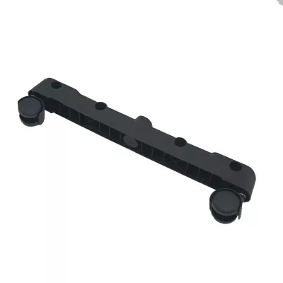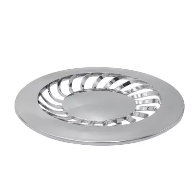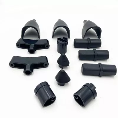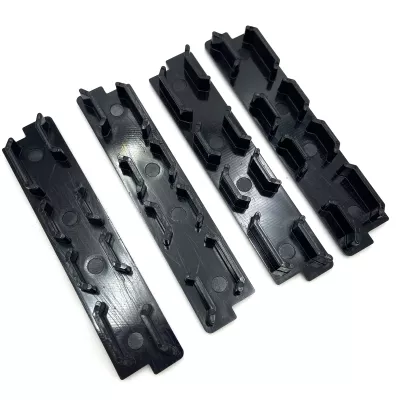
OEM ODM ABS PA66 Plastic Injection Parts | Custom Open Tray Housing Components
-
Model NumberS2405Plastic Modling TypeInjection
-
Processing ServiceMoulding, Cutting, PaintingCertificationISO9001 CE
-
MaterialPA66/PP/ABS /PC, EtcFeatureHigh Precision Injection Parts
-
Product namePlastic Injection PartsDrawing Format2D/(PDF/CAD)3D(IGES/STEP)
-
Surface treatmentPolish. Etched. Texture.electroplating.paintingColorCustomer's Request
-
ProcessInjection Mould Plastic PartApplicationIndustrial Plastic Parts
-
KeywordPlastic injection
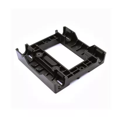
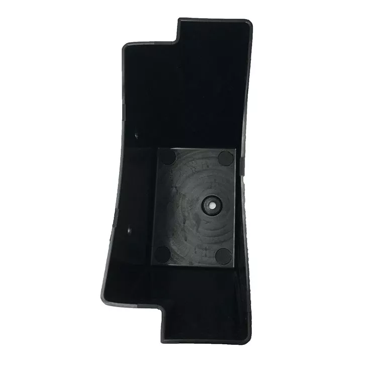
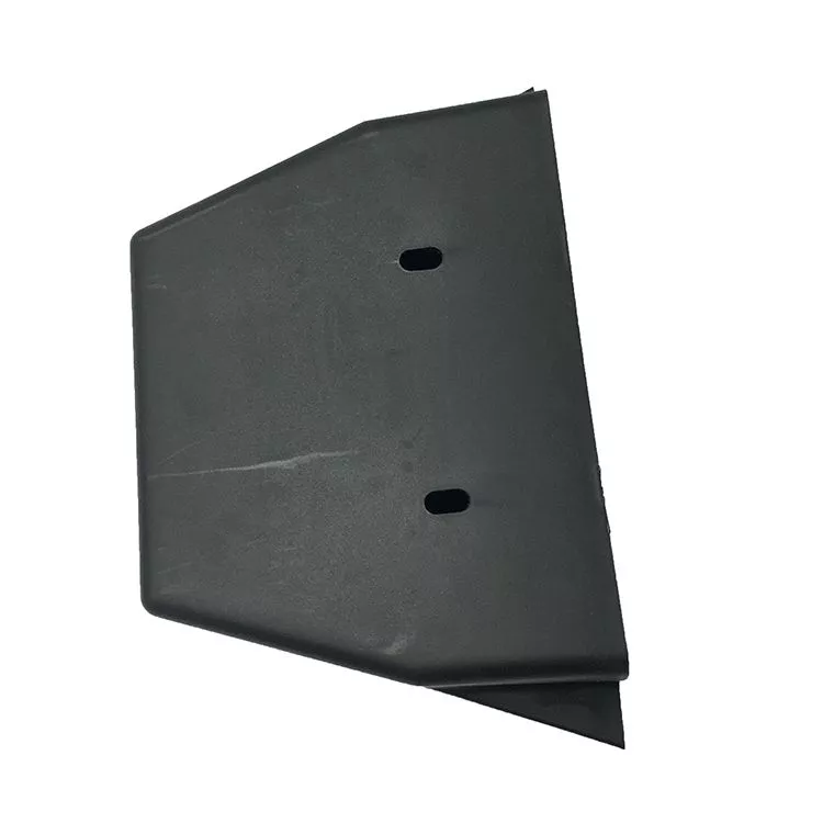
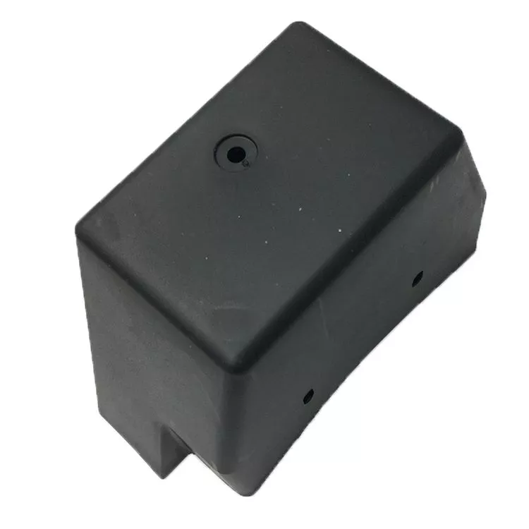
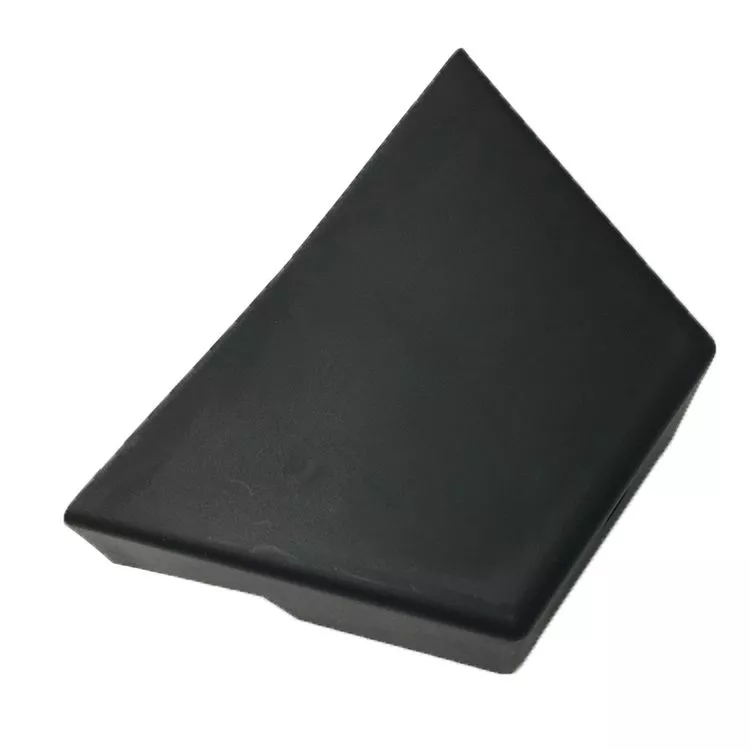
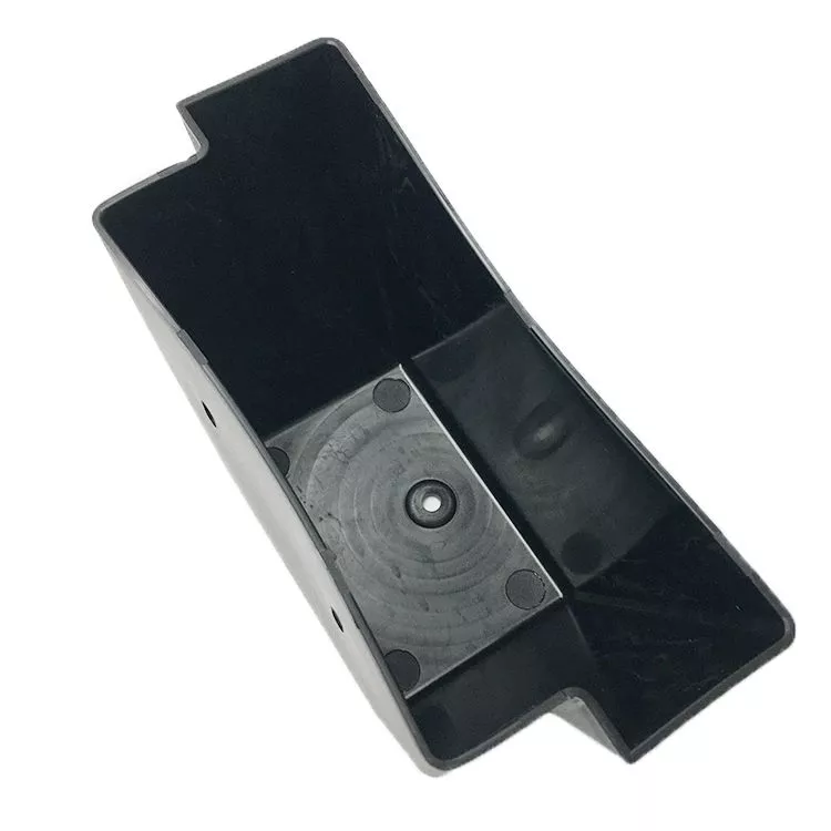
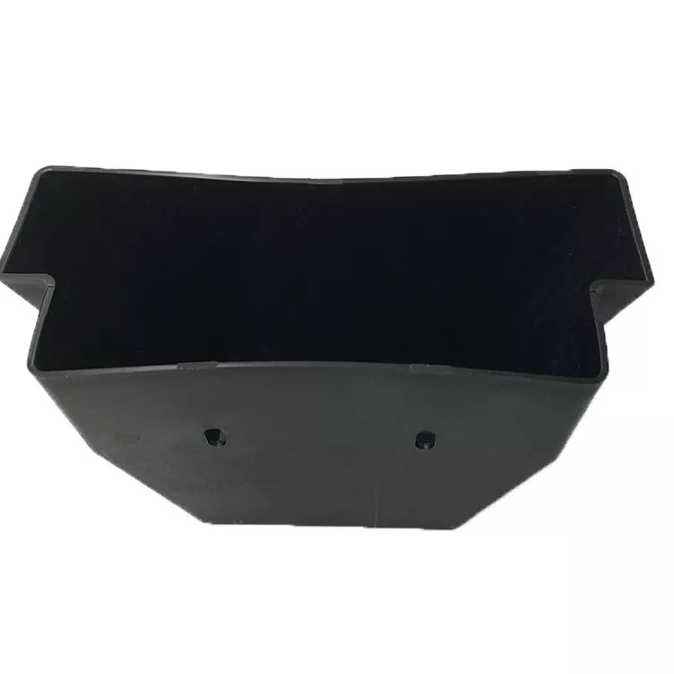
Define the open tray housing through its side walls, stepped ends and base fixing feature. The black example has a rectangular central region and raised perimeter surfaces. Its photograph does not establish actual dimensions or a numerical threshold for either large-part or small-part molding.
Locate the tray base and stepped perimeter
Provide sections showing wall geometry, fixing details and the actual mating contacts. Identify adjoining components and any clearances or retention requirements. Define whether the delivery includes the tray alone, a cover, inserts or hardware rather than treating an open housing image as a complete assembled enclosure.
- Reference the tray housing and actual dimensions.
- Locate base fixing and stepped-end interfaces.
- Choose the tray's actual ABS or polyamide formulation.
- Define color and compatible surface treatment.
- Agree dimensional and intended-use acceptance.
Select the resin and required finish
ABS and PA66 are separate material specifications; other listed plastics require their own selections. State the actual formulation, supplied condition and material documentation. Define polishing, texture, paint or another compatible treatment only where needed, with masking and appearance criteria at the working surfaces.
Inspect the housing against the assembly drawing
Mark tolerances with units, datums and final measurement conditions. Any mechanical, electrical or environmental requirement needs actual service conditions and applicable tests. A tray-like shape alone establishes neither load capacity nor suitability for a particular installation.
Include PDF/CAD or IGES/STEP geometry, quantities and requested inspection records. Keep size and component scope explicit so molding proposals are evaluated against the real design rather than general catalogue size labels.