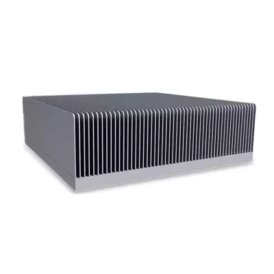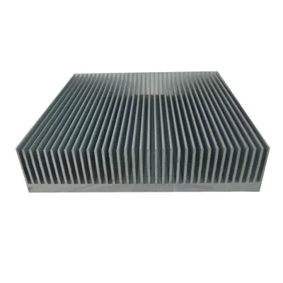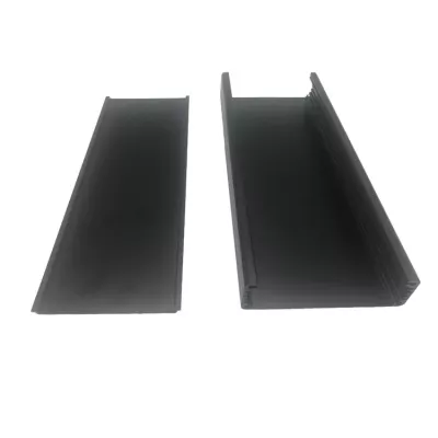
Custom Large High-Power Industrial Extruded Aluminum Profile Heatsink Enquiries
-
Grade6000 SeriesTemperT3-T8
-
ApplicationHeat SinkShapeAngle
-
Alloy Or NotIs AlloyModel NumberS2308
-
Tolerance0.02mm, ±0.02Processing ServiceBending, Decoiling, Welding, Punching, Cutting, Machining
-
Delivery Time15 daysMaterial6063/ 6061 etc
-
MachiningAvailableSurface treatmentAnodized/oxide etc /powder coated
-
ToolingMade by ourselfSurface ColorCustomized Panton Colors
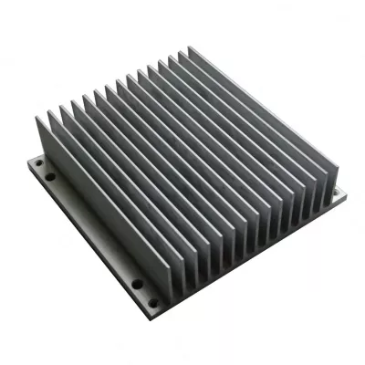
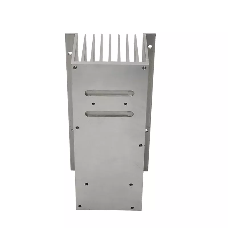
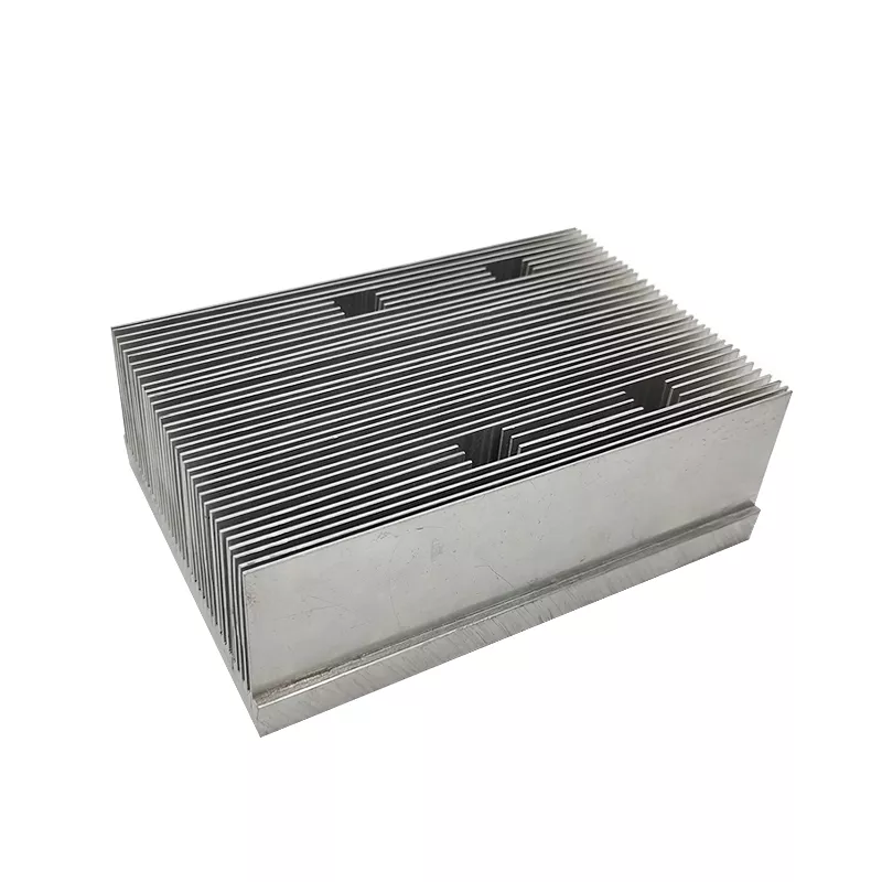
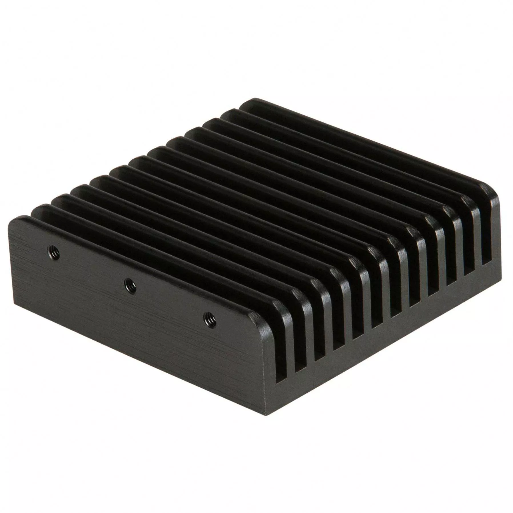
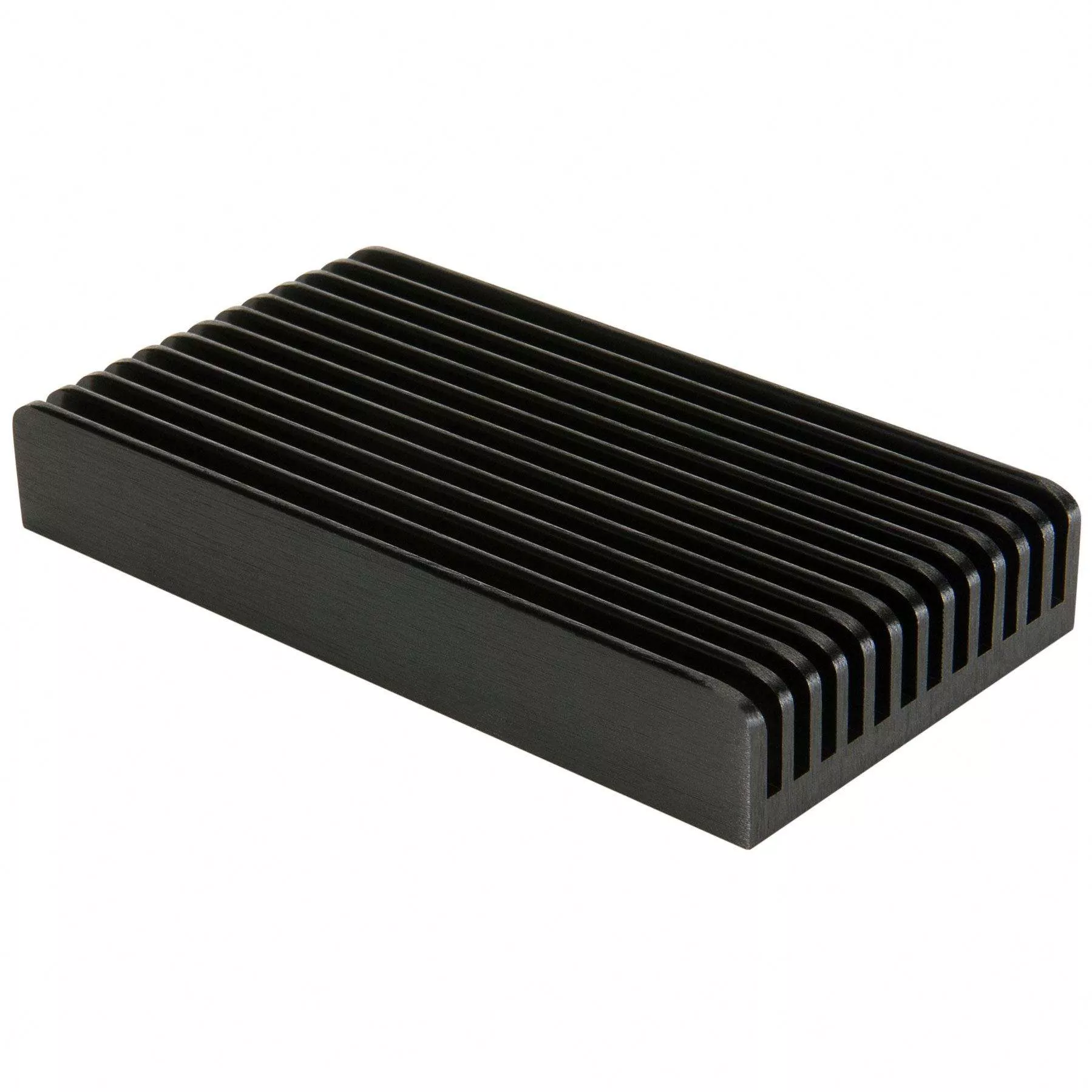
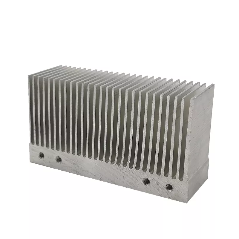
Use the intended installation to define a large industrial aluminum heat sink. The example is a tall rectangular plate-fin component with a broad lower base and fixing openings along the front edge. Large-size and high-power wording are design directions, not measured dimensions or an established wattage rating.
Dimension the envelope and mounting base
Provide the overall section, cut length and available installation space. Locate the base contact face and fixing holes from the assembly references. Dimension the fin height, spacing and any interfaces that control fit or clearance to adjoining equipment.
Identify the surfaces requiring machining and the condition in which the part will be supplied. A visible hole pattern does not establish compatibility with a particular industrial assembly. Include the mating drawing where it determines mounting or thermal contact.
Specify the actual material and finished limits
- Select the actual 6061 or 6063 alloy and temper.
- Provide the controlled base, fin-field and mounting drawing.
- Mark the contact face and required CNC features.
- Define finish, masking and final supplied condition.
- State dimensional inspection and thermal acceptance requirements.
The 0.02mm and ±0.02 references need affected dimensions, units and measurement methods before they can govern acceptance. They do not define the same precision for every fin and finished interface. Agree the profile and secondary-work route for the selected design rather than adopting every service in the general menu.
Make high-power requirements measurable
Supply the actual heat load, ambient conditions, airflow and the way the component meets the heat source. Identify the acceptance or evidence needed under those installation conditions. Neither apparent size nor a tall fin field establishes a tested cooling capacity. Confirm current quantities and the complete delivered scope for the selected drawing. A clear enquiry links the actual envelope and mounting geometry to one material, finish and inspection plan, allowing proposals to be compared on the same thermal and dimensional requirements.