-
Grade6000 SeriesTemperT3-T8
-
ApplicationHeat SinkShapeAngle
-
Alloy Or NotIs AlloyModel NumberS 2301
-
Tolerance0.02mm, ±0.02Processing ServiceBending, Decoiling, Welding, Punching, Cutting, Machining
-
Delivery Time15 daysMaterial6063/ 6061 etc
-
MachiningAvailableSurface treatmentAnodized/oxide etc /powder coated
-
ToolingMade by ourselfSurface ColorCustomized Panton Colors
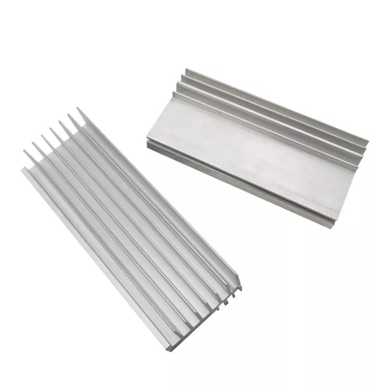
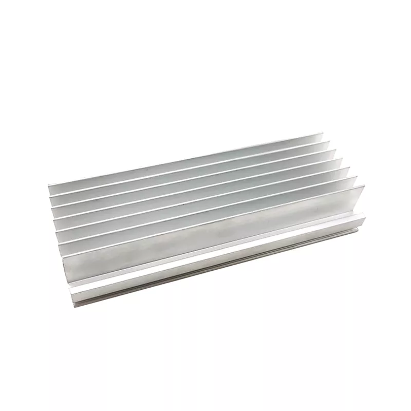
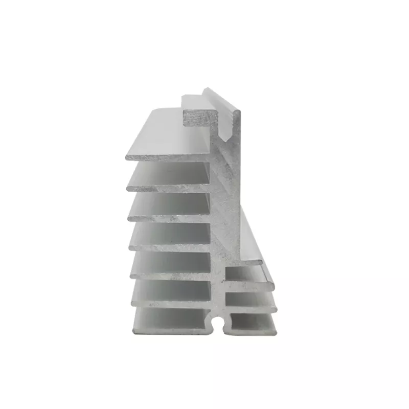
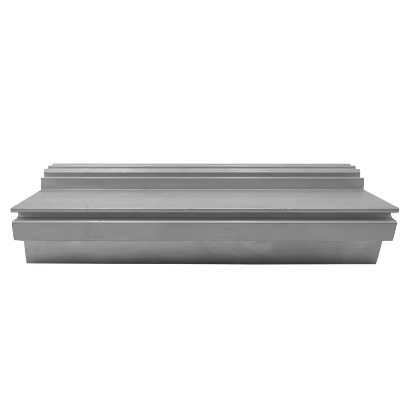
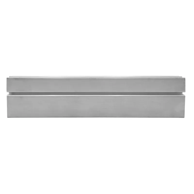
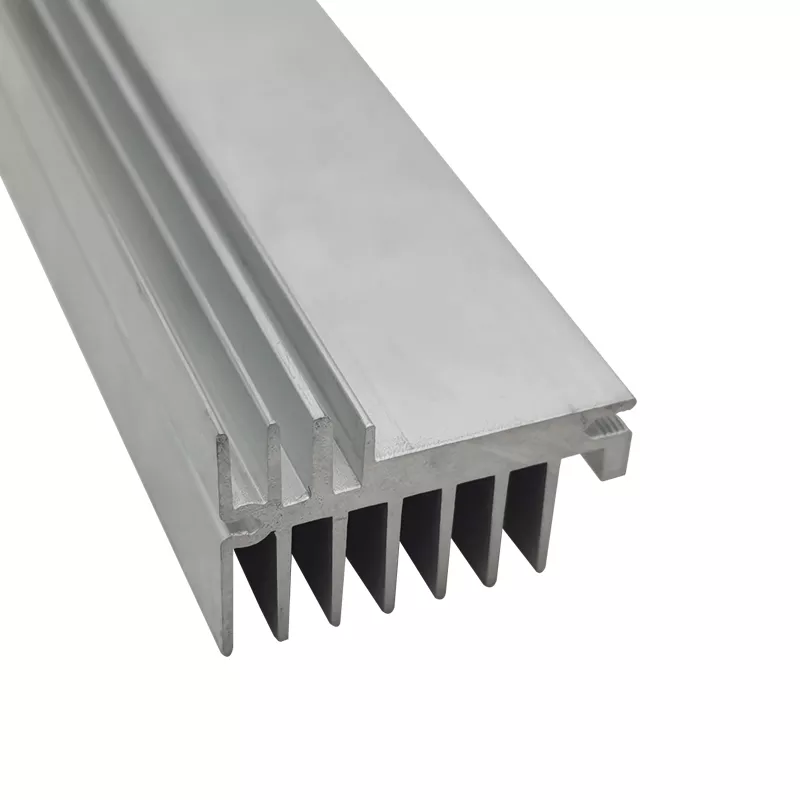
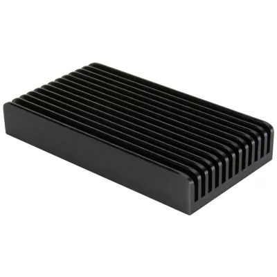
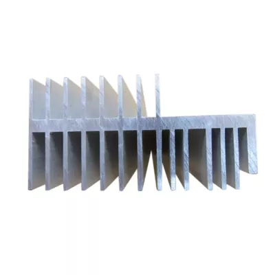
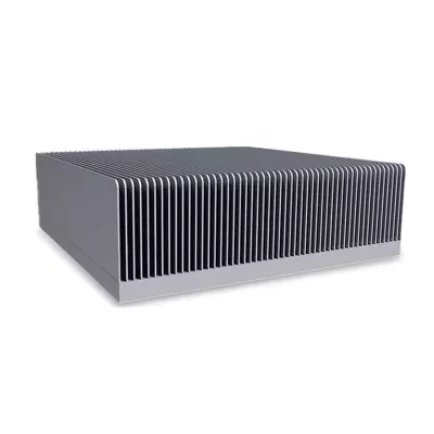
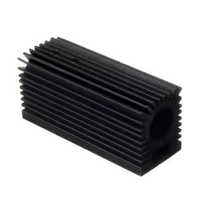
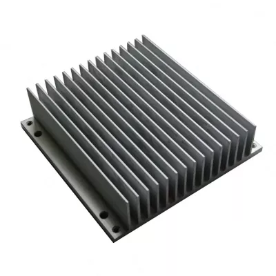
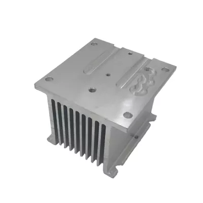
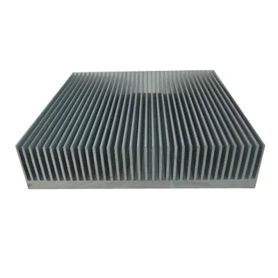
Define the heat-sink component required by the LED grow-light assembly rather than selecting it from appearance alone. The examples show two finned sections with different arrangements: one long piece with parallel fins and another broader plate-like form with fins concentrated near an edge. Identify the actual section and installation required by the project.
Locate the heat source and mounting interfaces
Provide the profile drawing, cut length and contact-face dimensions, with the fixing arrangement that joins the component to the assembly. Locate holes or machined faces from the drawing references. Include neighbouring parts where they limit clearance around the fins or access to the mounting features.
A heat-sink or grow-light title does not establish the thermal capacity of a particular installed component. The photograph also does not prove compatibility with a specific light, an electrical approval or any plant-growth result. State the actual assembly and thermal acceptance requirements relevant to the part being sourced.
Select the material and anodized finish
- Choose the actual 6061 or 6063 alloy and temper.
- Provide the selected fin section and cut length.
- Locate mounting features and the thermal contact face.
- Specify anodizing, color and any masking requirements.
- Define finished inspection and the supplied component scope.
The general temper and processing menus are options to review for the actual design, not a fixed instruction for every sample. Assign dimensional requirements to the features that control fit, identifying units and measurement conditions rather than assuming one tolerance for every fin and machined surface.
State the conditions for thermal assessment
Provide heat load, ambient conditions, airflow and the contact arrangement between the heat source and the component. Choose finish and contact-face requirements together so that the supplied condition is clear. Confirm current quantities and delivery arrangements for the selected drawing. The enquiry should connect one fin configuration to its actual mounting and thermal requirements, with the inspection records needed to accept the delivered part.